| 1.3. Abilis first steps | ||
|---|---|---|
 | Chapter 1. About Abilis CPX |  |
Here is your new Abilis. More or less it is a PC specialised to control your connections to the Internet and to the telephone-network. It acts also as your building automation system.

The first steps to operate the device are:
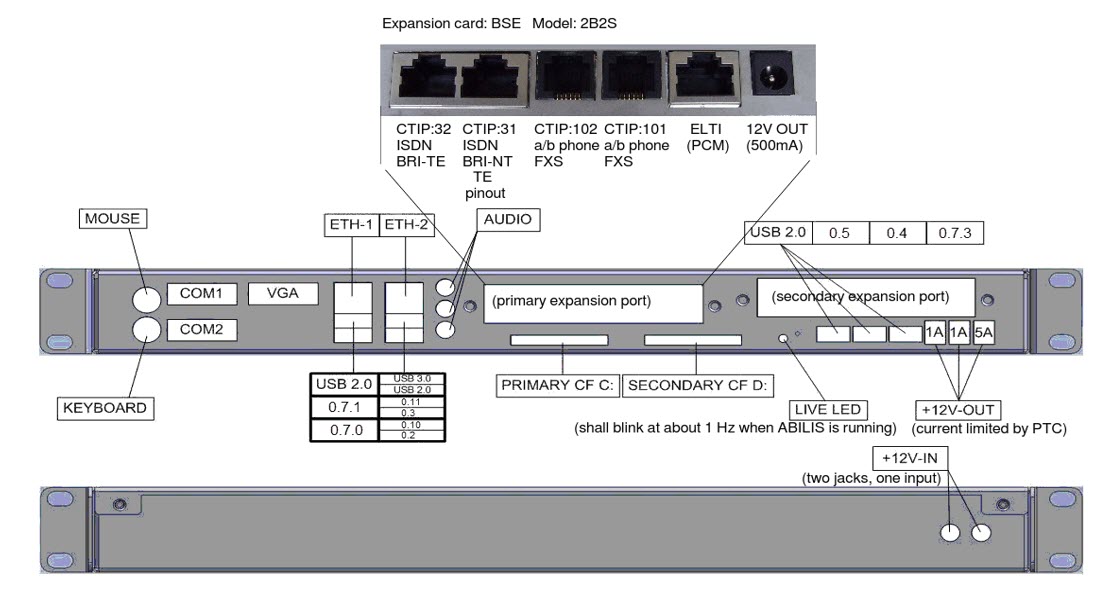
Plug the power cord into one of the two jacks in the rear panel. ABILIS can be switched-off at any time, without calling any shutdown procedure.
ABILIS requires about 2.5Amps @12 volts DC.
ABILIS does not have any power-switch, as it is intended to remain always on/running.
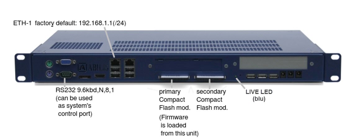
When ABILIS is powered on, a blue LED lights-up.
ABILIS can be switched-off at any time, without calling any shutdown procedure.
All the data: firmware, configuration-files, system LOGs and user-data are stored in the Compact-Flash modules. In case of large Databases, files can be stored in an additional internal storage. There is room for two 2.5” SSDs.
The boot process typically takes less than one minute.
The primary module is typically reserved for system-startup and storage of the main configuration-file. These files can be backed-up automatically onto the secondary module, at time intervals. In case of failure of the primary CF, the two modules can be slipped-out and exchanged.
As soon as the software is running, the blue LED starts to blink slowly, about once per second. Whenever the LED is blinking, the system is operating correctly.
In the event that problems are experienced, but the LED is blinking, please check the diagnostics and statistics of the ABILIS (or let them be checked by the remote help-desk), rather than powering the ABILIS off. The LED is driven by a watchdog which controls the correctness of the operations. In case of ‘exceptions’, it records the exception and restarts the ABILIS automatically.
Once the ABILIS is operational, the ‘command-line controls’ are available by means of:
TELNET (port 23) or SSH (port 22), with reference to the IP add of the chosen port.
Per default ETH-1 has the IP add/mask set to 192.168.1.1/255.255.255.0.
The access is granted to every user, using no password.
the RS232 serial port, set per default at 9.6kbps, N,8,1 (no password).
the web interface at http:192.168.1.1 ... but per default no user is active. To use the web pages, some preliminary system-configuration is required.
the keyboard and VGA ports can be used only to view the system startup and to display some very basic system information, using the up/down/right/left arrow-keys. These ports are not linked to the command-line.
Using the command line is less difficult than it may appear at
first-sight, however, this is a task for skilled technicians.
Therefore, let's write the list of requirements (objectives to reach)
and the description of the networking-environment where the ABILIS is
to be placed. On this base, ABILIS technicians will prepare a tiny
configuration file (DRIVERS.CFG) which they will
deliver you by e-mail.
DRIVERS.CFG is to be copied into the
primary compact-flash module, precisely into the Firmware-directory,
named «8-10-0».
BTW: the CF modules can be easily removed and re-inserted, but please take care to do this when the ABILIS is switched-off.
Your ABILIS might contain an optional PCI Board, typically containing ISDN or analogue telephony ports.
ISDN-BRI ports have the pinout of the user's devices (TE, terminal equipment). They can be programmed as Network-Terminations, as when the ABILIS replaces a Telecom ISDN line with a VoIP based equivalent. When used as NTs, ABILIS ports require a ‘cross cable’ exchanging the line's signals.
ISDN-PRI (S2M) ports have NT-pinout. They can be programmed and used as TE, by utilising the cross cable.
Analogue telephony ports can be directly available from the expansion board (up to four ports) or can be available in larger number (till to 32ports) by means of the ELTI port and of an expansion box (called «POTSBOX»), delivering the usual telephony (RJ11) jacks. Analogue ports can be configured to work with normal telephone-handsets, or with headphones, or with ‘public-address’ loudspeakers, or with ‘entry-phones’.
Details of your Abilis:
