| 2.8. Abilis PCI boards and extension boards | ||
|---|---|---|
 | Chapter 2. Abilis hardware |  |
| 2.8. Abilis PCI boards and extension boards | ||
|---|---|---|
| | Chapter 2. Abilis hardware | |
Abilis can be supplied with several PCI cards, as many as the mother board can host (up to 4 PCI slots). Here are the available cards:
Table 2.4. Abilis PCI boards and extension boards
| Card name | Function | Notes |
|---|---|---|
| ESB2 | 4 Serial Synchronous Ports, HDLC | Holds up to 4 modules (V24, V35, V11, X21, E1/G.703) |
| QPRIX | 4 ports Primary Rate ISDN | Stand-alone card |
| PB22 | 2 ports Primary Rate ISDN 2 ports Basic Rate ISDN | Stand-alone card |
| PB44X - PB44 | 4 ports Primary Rate ISDN 4 ports Basic Rate ISDN | Stand-alone card+ extension |
| BRI-HFC4 | 4 ports Basic Rate ISDN | Stand-alone card |
| BRI-HFC8 | 8 ports Basic Rate ISDN | Stand-alone card |
| POTS 4/8/16 | From 4 to 16 FXS analog channels | Can be supplied with CTI or BRI-HFC card |
| BSE | 1 ELTI, From 0 to 4 BRI and/or from 0 to 4 POTS | Stand-alone card |
| POTSHUB | 4 ports ELTI | Stand-alone card |
| Ethernet | IP router, Ethernet bridge | Stand-alone card |
| GigaEthernet | IP router, Ethernet bridge | Stand-alone card |
| QUAD-Ethernet | IP router, Ethernet bridge | Stand-alone card |
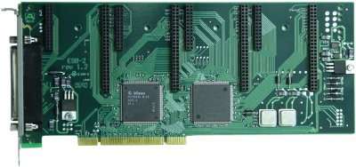
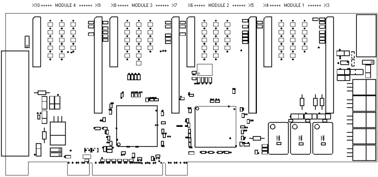
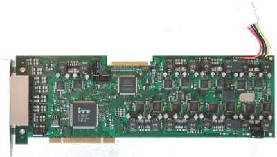
ESB2 card supplies Abilis with 4 synchronous ports you can configure up to 2,5 Mbps. They are generally used for CDN or HDSL connections.
As shown on the picture, the ESB2 card can hold up to 4 modules:
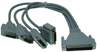
The modules are plug-to-plug compatible and can be hold in any arrangement. The external devices are connected to an “octopus” cable connected to the ESB2 card. This cable has 4 DB15 female connectors numbered from 0 to 3 which correspond to the 1 to 4 modules and a HDB-62 female connector to connect the card. These connectors will be connected to the corresponding adaptation cables V24/V35/X21/E1.
Each DB15 connector has 15 pins. The HDB-62 connector has 62 pins.
The adapter cable is made by 7 twisted pairs. The cable is shielded.
| Pin | ESB2 Connector pin - Port 0 | ESB2 Connector pin - Port 1 | ESB2 Connector pin - Port 2 | ESB2 Connector pin - Port 3 |
|---|---|---|---|---|
| 1 | 1 | 6 | 11 | 16 |
| 2 | 22 | 22 | 32 | 37 |
| 3 | 23 | 28 | 33 | 38 |
| 4 | 24 | 29 | 34 | 39 |
| 5 | 25 | 30 | 35 | 40 |
| 6 | 26 | 31 | 36 | 41 |
| 7 | 2 | 7 | 12 | 17 |
| 8 | 4 | 9 | 14 | 19 |
| 9 | 43 | 48 | 53 | 58 |
| 10 | 44 | 59 | 54 | 59 |
| 11 | 45 | 50 | 55 | 60 |
| 12 | 46 | 51 | 56 | 61 |
| 13 | 47 | 52 | 57 | 62 |
| 14 | 3 | 8 | 13 | 18 |
| 15 | 5 | 10 | 15 | 20 |
![[Note]](../images/note.png) | Note |
|---|---|
Pins 21 and 42 are not connected and can be used for the insertion key. |
The port pins will have different meaning in fuction of the interface modules installed as shows in the following table:
Table 2.5. Meaning of pins depending of the module model
| Couple(Twisted pair) | Port Pin (DB15) | Octopus wire color | V35/V11 | V24 | X21 | E1/T1 |
|---|---|---|---|---|---|---|
| 1 | Shield- no wire | Shield + Gnd | Shield | Shield + Gnd | unused | |
| First | 2,9 | Brown,White-Brown | TX+,TX- | TX,TXC | TX+,TX- | Txa,Txb |
| Second | 3,10 | Red,Black-Red | RX+,RX- | RX,RXC | C+,C- | Rxa,Rxb |
| Third | 4,11 | Yellow,Black-Yellow | TXC+,TXC- | RTS,DTECLK | RX+,RX- | unused,unused |
| Fourth | 5,12 | Green,Black-Green | RXC+,RXC- | CTS,DTR | I+,I- | unused,unused |
| Fifth | 6,13 | Blue,White-Blue | DTECLK+,DTECLK- | DSR,RI | CLK+,CLK- | unused,unused |
| Sixth | 7,14 | Light Blue,Light Blue-Blue | DTR,RTS | GND,unused | DTECLK+,DTECLK- | unused,unused |
| Seventh | 8,15 | Light Blue-Dark Green,Light Blue-Light Green | CTS,DCD | DCD,unused | unused,unused | unused,unused |
Abilis software numbers the synchronous ports as shown in the table:
Table 2.6. ESB2 modules and corresponding software resources
| HW Module | SW Resource |
|---|---|
| mod. 0 | SYNC-1 |
| mod. 1 | SYNC-2 |
| mod. 2 | SYNC-3 |
| mod. 3 | SYNC-4 |
![[Tip]](../images/tip.png) | Tip |
|---|---|
Interesting chapters:Section 68.5, “How to configure HDSL/SHDSL connections using V.35/G.703 synchronous ports” |
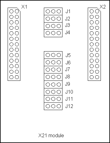
The X1 connector of the each interface module is inserted into X3, X5, X7 or X9 (depending on the module number) connector of the ESB2 card. The X2 connector of the each interface module is inserted into X4, X6, X8 or X10 (depending on the module number) connector of the ESB2 card.
Each module has two side:
the board side which is connected via X1 connector (50 pins);
the line side which is connected via X2 connector (26 pins).
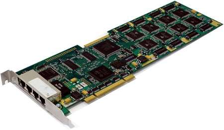
The QPRIX is a stand-alone card, it has 4 primary interfaces (ISDN-PRI) and supports up to 16 DSP for 64 compressed calls. Besides echo canceller (EC) is available up to 32 ms but it can raise up to 128 ms in the version with the additional Octasic chip (EEC).
Through H.100 bus it can also be connected to other cards of the CTI category.
For the ISDN-PRI (S2M) interfaces no standard physical port is specified. The Abilis QPRIX use RJ45 sockets with the same signal arrangement as the one used to access to BRI NT:
Table 2.7. QPRIx – RJ45 pinout
| Pin | Signal |
|---|---|
| 1 | N.C. |
| 2 | N.C. |
| 3 | Rx + (inbound) |
| 4 | Tx + (outbound) |
| 5 | Tx - (outbound) |
| 6 | Rx - (inbound) |
| 7 | N.C. |
| 8 | N.C. |
Each interface presents a 120 ohm balanced impedance. Each port can be configured as NT (Network Termination) or TE (Terminal Equipment).
Dimensions[mm]: 312x106;
Weight: 0.20Kg;
Table 2.8. Power consumption
| Condition | Condition | Consumption (mA) |
|---|---|---|
| Main 3.3 V regulator | After reset | 920 |
| Main 3.3 V regulator | After C6412 firmware upload | 1000 |
| Main 3.3 V regulator | After FPGA firmware upload | 1350 |
| Main 3.3 V regulator | After QFALC activation | 1560 |
| Main 3.3 V regulator | with 36 HDLC channels up&running | 1570 |
| Main 3.3 V regulator | with 64 AC channels up&running | 1990 |
| Main 3.3 V regulator | with all QFALC ports connected&performing traffic | 1630 |
| Audiocodes' 1.8 V regulator | After reset | 100 |
| Audiocodes' 1.8 V regulator | After KERNEL and PROGRAM download | 960 |
| Octasic's 1.8V regulator | After reset | 50 |
| Octasic's 1.8V regulator | After firmware download, during BIST | 140 |
| FPGA's 1.2 V regulator | Always | 330 |
| C6412's 1.2 V regulator | Always | 380 |
| C6412's 2.5 V regulator | Always | 60 |
The PB22X is a stand-alone card, it has 2X ISDN Primary Ports (ISDN30) and 2X ISDN Basic Ports (ISDN2)
Through H.100 bus it can also be connected to other cards of the CTI category.
The Abilis PB22 use RJ45 plugs with the following pinout for ISDN-PRI (S2M):
Table 2.9. PB22 – PRI RJ45 pinout
| Pin | Signal |
|---|---|
| 1 | N.C. |
| 2 | N.C. |
| 3 | Rx + (inbound) |
| 4 | Tx + (outbound) |
| 5 | Tx - (outbound) |
| 6 | Rx - (inbound) |
| 7 | N.C. |
| 8 | N.C. |
The Abilis PB22 use RJ45 plugs with the following pinout for ISDN-BRI:
Table 2.10. PB22 – BRI RJ45 pinout
| Pin | Signal |
|---|---|
| 1 | N.C. |
| 2 | N.C. |
| 3 | Tx + (inbound) |
| 4 | Rx + (outbound) |
| 5 | Rx - (outbound) |
| 6 | Tx - (inbound) |
| 7 | N.C. |
| 8 | N.C. |
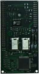
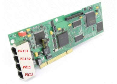
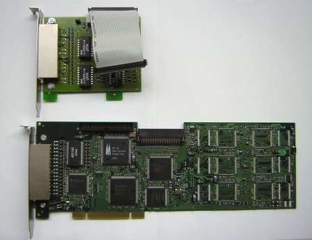
The PB44X card has 4 primary interfaces (ISDN-PRI) and, by means of a daugtherboard (BRI4ADD, see photo), 4 ISDN Basic Rate (ISDN-BRI) interfaces. All interfaces are freely configurable as NT / TE.
It supports up to 16 DSP for 64 compressed calls and can be connected to other CTI cards through the H.100 bus.
| Tip |
|---|---|
For information about the connection between Abilis and ISDN Basic Rate Interface (BRI) lines refer to Section 3.2, “ISDN Basic Rate Interface (BRI) connection”. |
The PB44X cards use RJ45 plugs with the following pinout, either on the main board (4 PRI ports) or on the extension (4 BRI ports).
Table 2.11. PB44X – RJ45 pinout
| Pin | Signal |
|---|---|
| 1 | N.C. |
| 2 | N.C. |
| 3 | Rx + (inbound) |
| 4 | Tx + (outbound) |
| 5 | Tx - (outbound) |
| 6 | Rx - (inbound) |
| 7 | N.C. |
| 8 | N.C. |
Each PRI interface presents a 120 ohm balanced impedance. Each port can be configured as NT (Network Termination) or TE (Terminal Equipment). The BRI ports have to use an impedance matching adapter.
![[Warning]](../images/warning.png) | Warning |
|---|---|
Although only one PCI slot is used for the electrical connection on the external part of the cabinet, the additional 4 BRI ports occupy an additional slot (for mechanical connection only). |
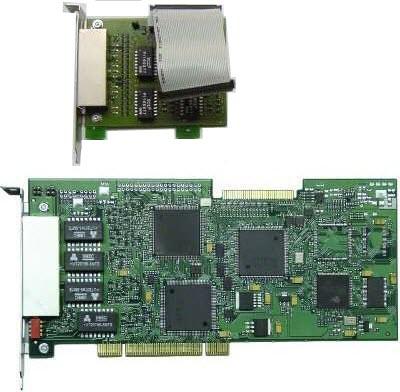
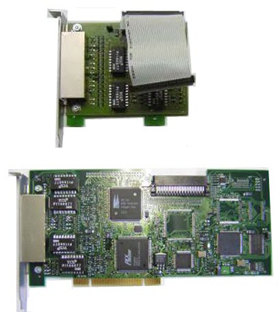
The PB44 card has 4 primary interfaces (ISDN-PRI) and, by means of a daugtherboard (BRI4ADD, see photo), 4 ISDN Basic Rate (ISDN-BRI) interfaces. All interfaces are freely configurable as NT / TE.
It supports up to 6 DSP for 24 compressed calls and can be connected to other CTI cards through the H.100 bus.
| Tip |
|---|---|
For information about the connection between Abilis and ISDN Basic Rate Interface (BRI) lines refer to Section 3.2, “ISDN Basic Rate Interface (BRI) connection”. |
The PB44 cards use RJ45 plugs with the following pinout, either on the main board (4 PRI ports) or on the extension (4 BRI ports).
Table 2.12. PB44 – RJ45 pinout
| Pin | Signal |
|---|---|
| 1 | N.C. |
| 2 | N.C. |
| 3 | Rx + (inbound) |
| 4 | Tx + (outbound) |
| 5 | Tx - (outbound) |
| 6 | Rx - (inbound) |
| 7 | N.C. |
| 8 | N.C. |
Each PRI interface presents a 120 ohm balanced impedance. Each port can be configured as NT (Network Termination) or TE (Terminal Equipment). The BRI ports have to use an impedance matching adapter.
| Warning |
|---|---|
Although only one PCI slot is used for the electrical connection on the external part of the cabinet, the additional 4 BRI ports occupy an additional slot (for mechanical connection only). |
The BRI-HFC4 card does the same work as a composite system made with: CTI board + BRI-4 (or BRI-8) module + DSP, but its cost is lower. It supports one/two DSP to manage four or eight simultaneous VoIP calls.
The DSPs now supports g.729 codec; besides all BRI-HFC cards are equipped with H100 bus.
| Tip |
|---|---|
For information about the connection between Abilis and ISDN Basic Rate Interface (BRI) refer to Section 3.2, “ISDN Basic Rate Interface (BRI) connection”. |
The BRI-HFC cards use RJ45 plugs with the following pinout :
Table 2.13. BRI-HFC – RJ45 pinout
| Pin | Signal |
|---|---|
| 1 | N.C. |
| 2 | N.C. |
| 3 | Rx + (inbound) |
| 4 | Tx + (outbound) |
| 5 | Tx - (outbound) |
| 6 | Rx − (inbound) |
| 7 | N.C. |
| 8 | N.C. |
Each is freely configurable (at the logical level) like NT (Network Termination) or TE (Terminal Equipment). The BRI ports require an impedance matching adapter.
| Tip |
|---|---|
Interesting chapters: Section 67.9, “How to know which kind of hardware is mounted on Abilis”. |
The BRI-HFC4 (BRI-HFC8) card does the same work as a composite system made with: CTI board + BRI-4 (or BRI-8) module + DSP, but its cost is lower. It supports one/two DSP to manage four or eight simultaneous VoIP calls.
Unlike BRI-HFC4/BRI-HFC8, the DSPs doesn't support g.729 codec; besides all old model of BRI-HFC cards are available in two versions:
equipped with H100 bus
not equipped with H100 bus
| Tip |
|---|---|
For information about the connection between Abilis and ISDN Basic Rate Interface (BRI) refer to Section 3.2, “ISDN Basic Rate Interface (BRI) connection”. |
The BRI-HFC cards use RJ45 plugs with the following pinout :
Table 2.14. BRI-HFC – RJ45 pinout
| Pin | Signal |
|---|---|
| 1 | N.C. |
| 2 | N.C. |
| 3 | Rx + (inbound) |
| 4 | Tx + (outbound) |
| 5 | Tx - (outbound) |
| 6 | Rx − (inbound) |
| 7 | N.C. |
| 8 | N.C. |
Each is freely configurable (at the logical level) like NT (Network Termination) or TE (Terminal Equipment). The BRI ports require an impedance matching adapter.
| Tip |
|---|---|
Interesting chapters: Section 67.9, “How to know which kind of hardware is mounted on Abilis”. |
The POTS cards belong to the CTI family and are used to connect analog telephone to the Abilis system. POTS are available with 4 , 8 or 16 FXS (BCA) interfaces. Through the H.100 bus, when installed on the same Abilis, several POTS cards behave like a single module (it works also with CTI or BRI-HFC cards). In this way Abilis becomes a powerful PBX system.
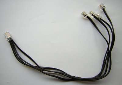
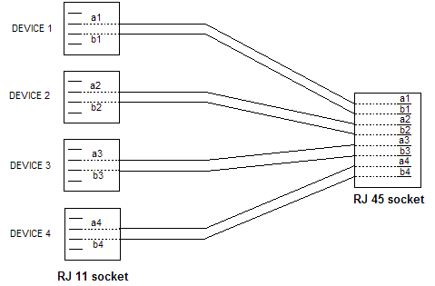
POTS cards have four RJ45 sockets. Each socket is to be used with an octopus cable (one RJ45 plug <-> four RJ11 plugs). Each RJ11 is for one telephone.
The octopus for POTS use the following pinout.
Table 2.15. Octopus cable pinout
| RJ45 Pin | RJ11 Pin |
|---|---|
| 1 (a1) | DEVICE 1 #1 - 1 |
| 2 (b1) | DEVICE 1 #1 - 2 |
| 3 (a2) | DEVICE 2 #2 - 1 |
| 4 (b2) | DEVICE 2 #2 - 2 |
| 5 (a3) | DEVICE 3 #3 - 1 |
| 6 (b3) | DEVICE 3 #3 - 2 |
| 7 (a4) | DEVICE 4 #4 - 1 |
| 8 (b4) | DEVICE 4 #4 - 2 |
| Note |
|---|---|
A variable delay to the start of ring signals is used to prevent a current overload in case of multicast groups with large number of Pots ports. The delay is in range of 20 to 140 msec. |
This board allows to protect POTS ports from external overvoltages and overcurrents such as the ones generated from lightnings.
Its equipped with:
four RJ45 which must be connected to the POTS 4/8/16 card;
four RJ45 which must be connected to the POTS phones.
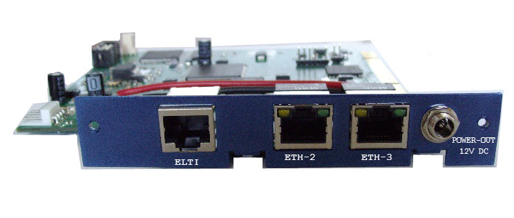
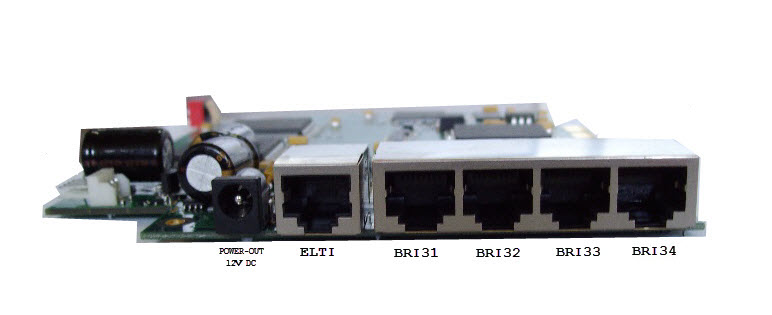
The BSE20 is a PCI card equipped with 1xRJ45 connector for Abilis proprietary ELTI (External LVDS TDM interface) interface, 2xRJ45 Ethernet ports and POWER-OUT connector useful to supply POTSBOX .The ELTI interface is used to connect the POTSBOX chassis which offers up to 32 POTS interfaces.
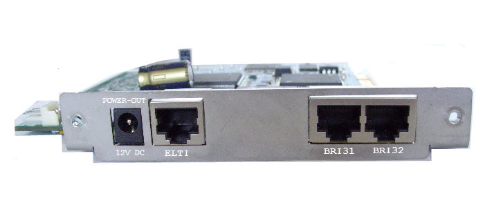
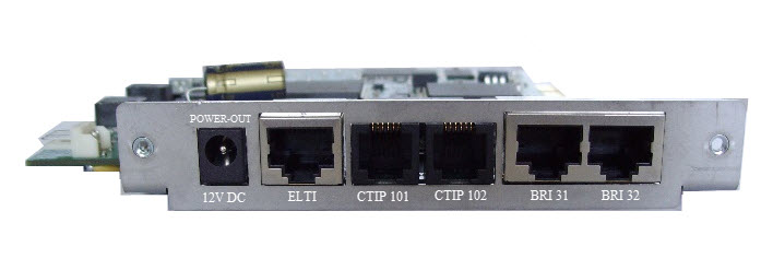
The BSE26 is a PCI card equipped with 1xRJ45 connector for Abilis proprietary ELTI (External LVDS TDM interface) interface, 2X ISDN Basic Ports (ISDN-BRI) and POWER-OUT connector useful to supply POTSBOX or and with 2X POTS ports .The ELTI interface is used to connect the POTSBOX chassis which offers up to 32 POTS interfaces.
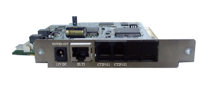
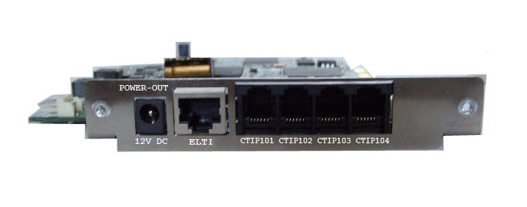
The BSE28 is a PCI card equipped with 1xRJ45 connector for Abilis proprietary ELTI (External LVDS TDM interface) interface, 2X or 4X POTS ports and POWER-OUT connector useful to supply POTSBOX .The ELTI interface is used to connect the POTSBOX chassis which offers up to 32 POTS interfaces.
The BSE29 is a PCI card equipped with 1xRJ45 connector for Abilis proprietary ELTI (External LVDS TDM interface) interface, 4X ISDN Basic Ports (ISDN-BRI) and POWER-OUT connector useful to supply POTSBOX .The ELTI interface is used to connect the POTSBOX chassis which offers up to 32 POTS interfaces.
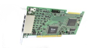
The POTSHUB is a PCI card equipped with 1xH.100 connector (internal) and 4xRJ45 connectors (external) for Abilis proprietary ELTI (External LVDS TDM interface) interface .The ELTI interface is used to connect the POTSBOX chassis which offers up to 32 POTS interfaces. Up to 4 POTSBOX can be connected to a POTSHUB card, and up to 3 POTSHUB card can be installed for a maximal of 384 POTS ports.
| Tip |
|---|---|
Interesting chapters: |
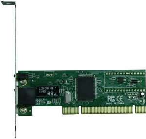
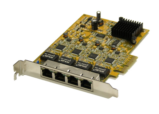
The Ethernet card provides a Fast Ethernet interface with Auto-Mode (10–100 Mbps) and Auto-TP (signals polarity) features. Several Ethernet cards can be installed into the same CPX.
| Tip |
|---|---|
Interesting chapters: Section 20.3, “IP Resources”; Section 68.2, “How to activate a new ethernet port”. |
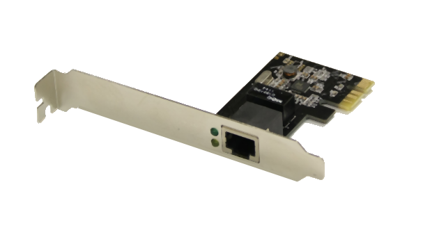
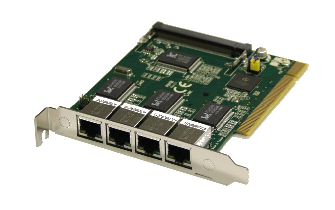
The GigaEthernet card provides a Gigabit Ethernet interface with Auto-Mode (10/100/1000 Mbps) and Auto-TP (signals polarity) features. Several GigaEthernet cards can be installed into the same CPX.
| Tip |
|---|---|
Interesting chapters: Section 20.3, “IP Resources”; Section 68.2, “How to activate a new ethernet port”. |
| |  | |
| 2.7. MFIDE module |  | 2.9. USB devices |