| 2.16. Remote devices | ||
|---|---|---|
 | Chapter 2. Abilis hardware |  |
| 2.16. Remote devices | ||
|---|---|---|
| | Chapter 2. Abilis hardware | |
This device is used to handle up to:
4 Digital Inputs;
4 Digital Outputs;
1 telecamera.
RVS is connected to Abilis via Ethernet interface.
![[Note]](../images/note.png) | Note |
|---|---|
The RVS is supported starting from Abilis firmware version 8.4. |
This device is used to handle up to:
16 Digital Inputs;
16 Digital Outputs;
8 Analog Inputs;
8 Analog Outputs.
RIO is connected to Abilis via Ethernet interface.
| Note |
|---|---|
The RIO is supported starting from Abilis firmware version 8.4. |
![[Tip]](../images/tip.png) | Tip |
|---|---|
Interesting chapters: Section 3.14, “RIO connection”; Section 21.3.2, “Activating the RIO device”; Section 82.2.1, “Example of LUA Script to pilot digital outputs of RIO device”; |
RIO device is produced in more Boards types:
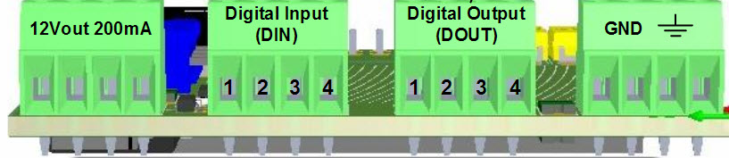
RIO Board-0, embedded with 4 Digital Inputs and Digital Outputs.
| Tip |
|---|---|
Physical connection of RIO Board-0 is identical with RVS, please see: Section 3.13, “RVS connection”. |
RIO Board-1, available in more subtypes.
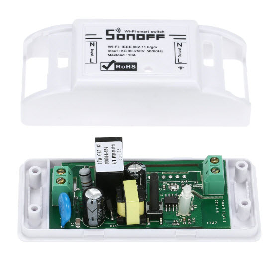
RIO Sonoff available in more subtypes.
| Note |
|---|---|
RIO Sonoff devices are supported starting from Abilis firmware version 8.7. |
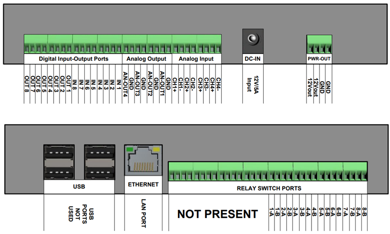
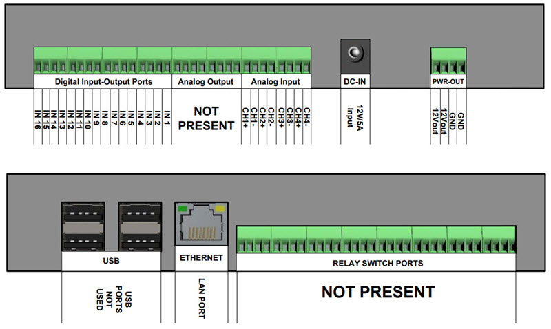
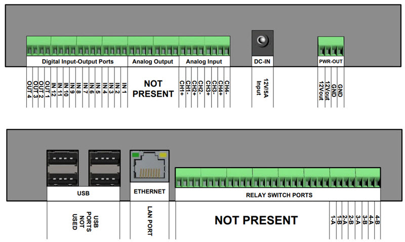
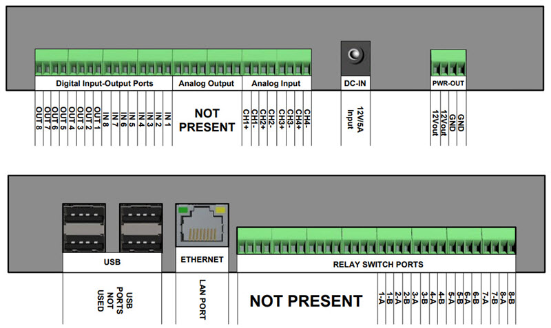
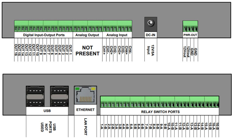
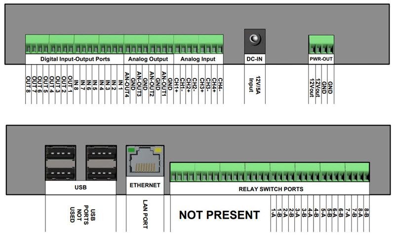
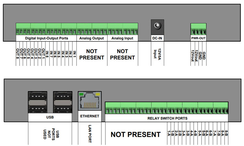
RIO device is available in more subtypes:
Below the pin mapping for these subtypes:
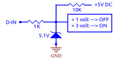
Digital Input (D-IN)The input ports are normally kept at 5V by means of a 10Kohm resistor. The logic value is ON. By connecting the input port to GND, the value goes OFF.
| Tip |
|---|---|
Interesting chapter: Section 3.14.1.2, “Connecting a motion sensor to Digital Input”. |
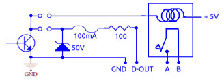
Digital Output (D-OUT)You can choose whether to use the relay output ("clean contact" A-B), or the output "open collector" supplying with power +5 ... +12V with a max current of 100mA.
| Tip |
|---|---|
Interesting chapter: Section 3.14.1.1, “Connecting an external relay to Digital Output”. |
Relay SwitchLimit values: max switched voltage 220V DC, 250V AC; max switching power 30W or 62W; switched current 1A. The ON logic value corresponds to the closed contact.
| Tip |
|---|---|
Interesting chapter: Section 3.14.1.3, “Connecting a DC motor to Relay Switch Port”. |
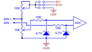
Analog Input (A-IN)These input ports are differential: they measure the
voltage difference between line + and
line - but it is necessary, however, that
the potential difference of each line with respect to GND
does not exceed 4.5 volts.
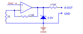
Analog Output (A-OUT)These output lines refer to GND. The output signal is adjustable between 0 and 10 V DC at 0.1V steps.
DC-INPower connector. Input 12V - 5A.
PWR-OUTPower sources for external sensors and actuators. The V-OUT is limited to 1A for each terminal. The GND must be used as a common ground reference for the various Input and Output lines.
LANEthernet 10M/100M auto-sensing. Support TCP/IP exclusively using the Abilis protocol.
USBWith the current firmware, ports are not used.
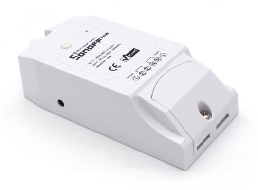
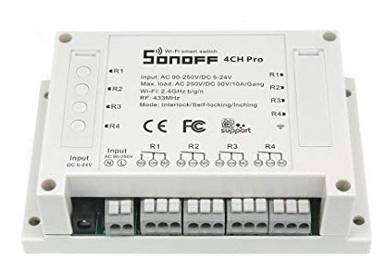
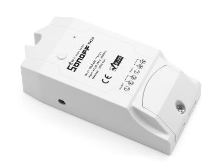
RIO Sonoff device is available in more subtypes:
Table 2.21. RIO Sonoff subtypes
| Subtype | Digital Inputs | Digital Outputs/Relay Switch | Analog Inputs | Analog Outputs |
|---|---|---|---|---|
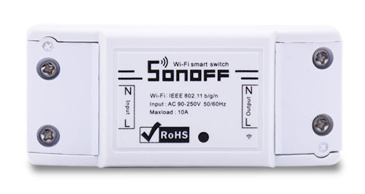
| Sonoff Basic R2 V1.0 | 0 | 1 | 0 | 0 |
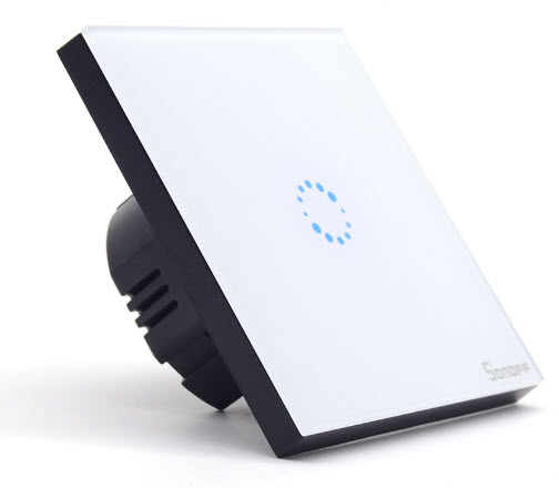
| Sonoff Touch EU WIFI V1.0 | 0 | 1 | 0 | 0 |
| Sonoff POW V2.0 | 0 | 1 | 3 | 0 |
| Sonoff 4CH Pro V1.1 | 0 | 4 | 0 | 0 |
| Sonoff TH10/16 without sensors | 0 | 1 | 0 | 0 |
| Sonoff TH10/16 V1.1 with DS18B20 | 0 | 1 | 1 | 0 |
| Sonoff TH10/16 V1.1 with AM2301 | 0 | 1 | 2 | 0 |
| Sonoff TH10/16 V1.1 with Si7021 | 0 | 1 | 2 | 0 |
Below the pin mapping for these subtypes:
One of the LEDs on the device is used to signal the configuration status:
When the LED blinks fast (about 5 times per second) it means that the device is not yet connected to the Access Point, this could happen because the AP has not been configured yet (see RIO Sonoff WiFi Configuration) or in the first seconds of the boot process when the device is attempting the connection to the AP.
When the LED blinks slowly (about 1 time per second) it means that the networking parameters of the device has not been configured yet using Abilis.
[version >= 1.1] When the LED is fixed ON it means that the device passed from initial programming state, where WiFi AP is NOT configured and a webserver is waiting for WiFi AP configuration, to dead state, where the webserver is stopped and the device is no more in AP mode.
On Sonoff Touch EU WIFI V1.0 the LED fixed ON has also a different meaning: during normal usage the LED is ON when the load is off.
[version >= 1.2] When the LED blinks fast 2 times every 5 seconds it means that the AP is configured but the device hasn't found it yet.
[version >= 1.2] When the LED blinks fast 4 times every 5 seconds it means that the device is able to find the AP but the authentication fails.
The button on the device (the first one on devices with more than one button) is used to:
Reboot the device: press the button for more than 2 seconds.
Clear the device configuration (networking and WiFi AP): press the button for more than 10 seconds.
Sonoff Touch EU WIFI V1.0 switch the relay status: press the button for less than 2 seconds.
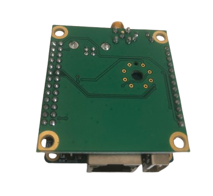
With Wireless input/output devices it is possible to arrange Wireless Sensor Networks (WSN). The project aims to provide analog and digital I/O wireless devices to create low speed, long range point-to-multipoint wireless networks, to let a thousand (or more) of tiny client-stations to interact reliably and securely with a central server-controller. A large number of wireless sensor nodes can manage and monitor the environment in a certain area; they can be connected to one or more WIO devices, the concentrator stations which act as control unit and that are connected via Internet to Abilis. Abilis deals with the processing, analysis and archiving of data and of the consequent leadership of any action that may become necessary.
There are 5 different boards with different functionalities:
Table 2.22. WIO subtypes
| Subtype | Digital Inputs | Digital Outputs/Relay Switch | Analog Inputs | Analog Outputs |
|---|---|---|---|---|
| MASTER | 0 | 0 | 0 | 0 |
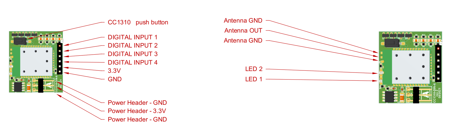
| Slave DIN 4 | 4 | 1 | 0 | 0 |
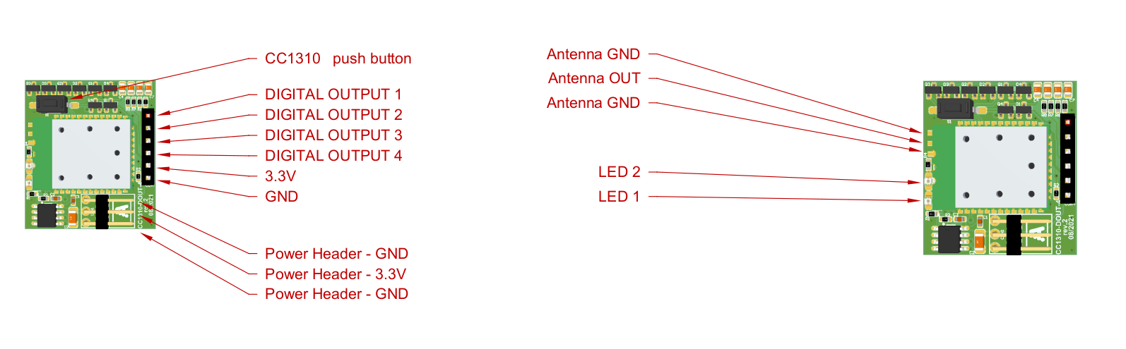
| Slave DOUT 4 | 0 | 4 | 0 | 0 |
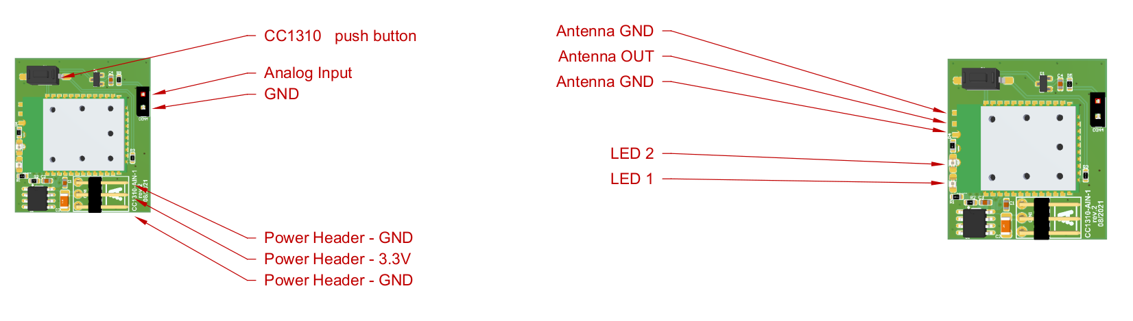
| Slave AIN 1 | 0 | 0 | 1 | 0 |
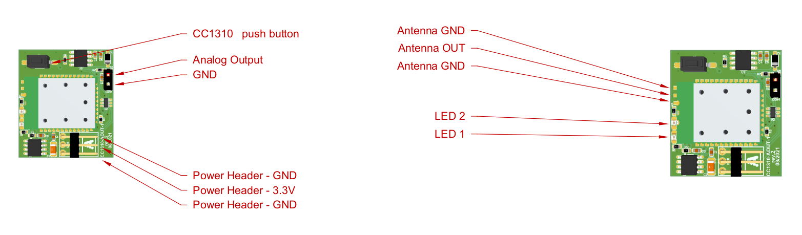
| Slave AOUT 1 | 0 | 0 | 0 | 1 |
WIO MASTER is connected to Abilis via Ethernet interface.
| Note |
|---|---|
The WIO is supported starting from Abilis firmware version 9.0. |
| Tip |
|---|---|
Interesting chapters: Section 21.3.2, “Activating the RIO device”; Section 82.2.1, “Example of LUA Script to pilot digital outputs of RIO device”; |
Short press (more than 100ms): enable the LED for 60 seconds;
Press longer than 2 seconds: put the NODE into programming mode for 10 seconds;
Press longer than 5 seconds: reboot the NODE;
Press longer than 10 seconds: reset the NODE configuration and reboot the NODE.
The LED on the NODE is always OFF, when the button is pressed for less than 2 seconds, the LED starts to show the NODE state for 60 seconds:
LED blinks every second: the NODE is configured and connected to MASTER;
LED is always OFF: the board is not configured/connected to MASTER or the board is not working properly;
LED is always ON: the NODE is in programming mode.
| |  | |
| 2.15. ELTI devices |  | 2.17. Ethernet devices |