| 3.8. Citobox connection | ||
|---|---|---|
 | Chapter 3. Physical connections |  |
| 3.8. Citobox connection | ||
|---|---|---|
| | Chapter 3. Physical connections | |
![[Tip]](../images/tip.png) | Tip |
|---|---|
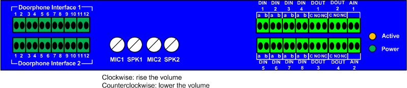
Click here to view the front panel pinout. |
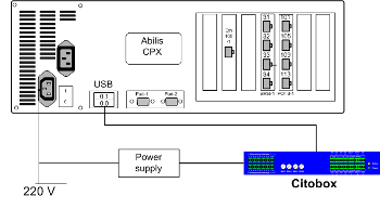
Follow the steps below to connect a Citobox:
Power on Abilis;
connect the Citobox to Abilis using the USB cable;
connect the power supply to Citobox;
| Tip |
|---|---|
Interesting chapters: |
Antek recommends to use the following doorphone systems because they have been tested.
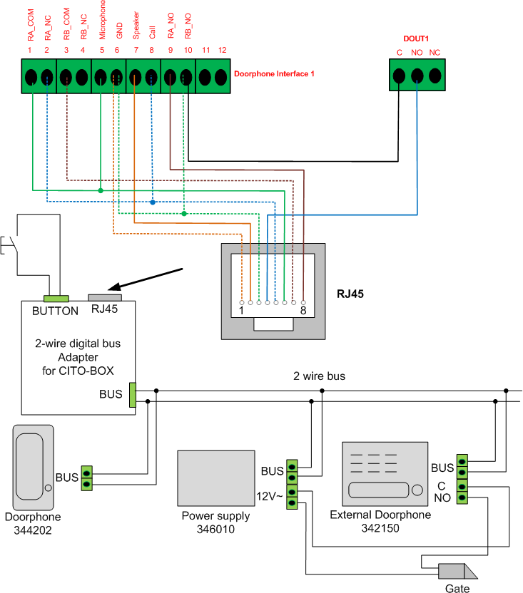
This section explains physical connection between Citobox and Bticino 2 wire digital bus.
connect power to Citobox using the port on the rear;
connect Abilis to Citobox using the usb port on the rear;
use a RJ45 plug to connect the door phone interface and the digital output on the front panel to the digital bus adapter following the scheme below;
connect the digital bus Adapter for CITO-BOX to the doorphone system using 2-wire bus as explained in the following scheme.
| Tip |
|---|---|
Click here to view the front panel pinout. |
configure the highlighted parameters of the cti port #241:
[13:41:05] ABILIS_CPX:d p ctip:241

CTIP:241 DESCR:
Act     card:CB-1<1>
Run     OPSTATE:UP        LOG:NO                               TYPE:USER
        signalling:CITO
        mode:CITO                                    NUM:999901
        MORE-BUTTONS:1,2,3,4
        L1-ON:   L1-OFF:   L1-PULSE:   L1-PULSE-T:1000       L1-PULSE-GAP:250
        L2-ON:   L2-OFF:   L2-PULSE:   L2-PULSE-T:1000       L2-PULSE-GAP:250
        L3-ON:   L3-OFF:   L3-PULSE:   L3-PULSE-T:1000       L3-PULSE-GAP:250
        L4-ON:   L4-OFF:   L4-PULSE:   L4-PULSE-T:1000       L4-PULSE-GAP:250
        CITO-GAIN-IN:SYS         CITO-GAIN-OUT:SYS
        CITO-ES:SYS
        CITO-ES-RISE-OUT:SYS     CITO-ES-FALL-OUT:SYS     CITO-ES-THR-OUT:0
configure the CITOBOX section of the CTISYS resource in the following way:
[02:22:47] ABILIS_CPX:d p ctisys

RES:CtiSys --------------------------------------------------------------------
Run    DESCR:CTI_System_general_properties
...
       - CITOBOX defaults -----------------------------------------------------
       CITO-GAIN-IN:0            CITO-GAIN-OUT:0
       CITO-ES:NO
       CITO-ES-RISE-OUT:20       CITO-ES-FALL-OUT:200      CITO-ES-THR-OUT:-12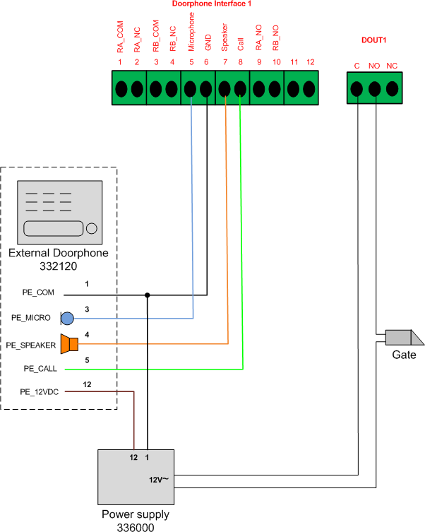
...This section explains the physical connections between Citobox and Bticino 4 wire analog bus.
connect the power to Citobox using the port on the rear;
connect the Abilis to Citobox using the usb port on the rear;
check that you have an adapter cable like the one shown in the picture below, with a RJ45 plug at one end and two terminal blocks at the other end. This cable is necessary to connect the doorphone interface and the digital output on the front panel to the digital bus adapter;
| Tip |
|---|---|
Click here to view the front panel pinout. |
connect the digital bus adapter for the CITO-BOX to the doorphone system using a 2-wire bus as explained in the following scheme.
| |  | |
| 3.7. UMTS-BOX connection |  | 3.9. Simbox connection |