| 3.10. RJS connection | ||
|---|---|---|
 | Chapter 3. Physical connections |  |
The following figure explains how to connect the ports:
Follow the steps below to connect a RJS:
Power on Abilis;
connect the switch to Abilis using the USB cable;
connect the power supply to RJS;
![[Tip]](../images/tip.png) | Tip |
|---|---|
Interesting chapters: |
Before reading examples just keep in mind the following notes:
only the central pins 4,5 and 3,6 are switched;
pins 1,2 and 7,8 are not connected.
RJS can be used to connect two Abilis:
A main Abilis;
A backup Abilis.
The backup device is always in idle unless the master crashes. The following is the scheme to use:
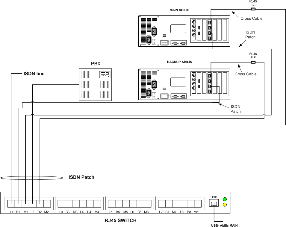
When Abilis MAIN is up the ISDN line is connected to M1 and so to ctip port #33 of Abilis MAIN. A call is routed through the port #31 connected to M2, so it reaches the PBX (L2).
When Abilis MAIN is down, L1 is automatically switched on B1 (which is connected to ctip port #33 of Abilis BACKUP) and L2 is switched on B2. A call is routed through the port #31 (of Abilis BACKUP) connected to B2, so it reaches the PBX (L2).
![[Tip]](../images/tip.png) | Tip |
|---|---|
Interesting chapter: Section 3.10.2, “Connection cables”. |
RJS can be used to automatically bypass Abilis when it's down and connect an ISDN line directly to a PBX.
The following is the scheme to use:
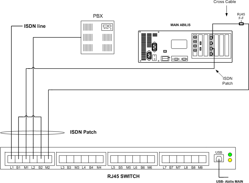
When Abilis is up:
The ISDN line is connected to ctip #33 because L1 is switched on M1;
The PBX is connected to ctip #31 because L2 is switched on M2.
A call from the ISDN line reaches Abilis which routes it through the port #31, so the call reaches the PBX.
When Abilis is down:
The ISDN line is connected directly to the PBX, because L1 is switched on B1 and L2 is switched on B2.
A call from the ISDN line reaches directly the PBX.
RJS can be used to switch ADSL lines. Up to 2 ADSL lines can be connected to a single port because only the central pins 4,5 and 3,6 are switched (remaining pins 1,2 and 7,8 are not connected).
![[Note]](../images/note.png) | Note |
|---|---|
There must be one ADSL modem for one line and one ADSL modem for each Abilis (MAIN and BACKUP). So four modems are needed to connect two ADSL lines to RJS having two Abilis (MAIN and BACKUP). |
Use the following scheme to connect 2 ADSL lines:
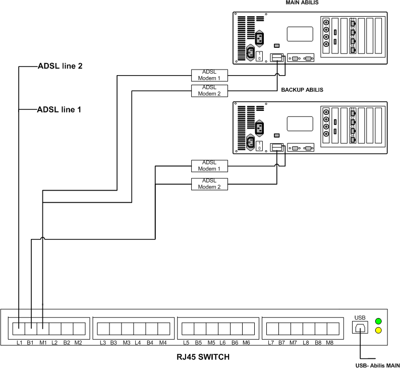
When Abilis MAIN is up, the ADSL lines are connected to M1, so they're used by Abilis MAIN.
When Abilis MAIN us down, the ADSL lines are switched to B1 and they're connected to Abilis BACKUP.
![[Caution]](../images/caution.png) | Caution |
|---|---|
RJS isn't suitable to connect HDSL lines with V35 interfaces. |
RJS can be used to connect Ethernet cables knowing that: only central pins 4,5 and 3,6 are switched (remaining pins 1,2 and 7,8 are not connected). So:
Ethernet cables which use pins 1,2 and 7,8 can't be connected;
Ethernet cables can be connected but adapter cables must be used.
The adapter cable must be made so that pins 1,2 are connected to pins 4,5 and pins 3,6 remain connected to pins 3,6.
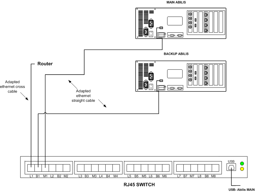
When Abilis MAIN is up, the cross cable is switched on the M1 and so Abilis MAIN is connected to the router.
When Abilis MAIN is down, the cross cable is switched to B1 and so Abilis BACKUP is connected to the router.
RJS can be used to switch ELTI (External LVDS TDM interface) lines. The ELTI port uses all 8 pins unlike the RJS, which uses only central pins 4,5 and 3,6 (remaining pins 1,2 and 7,8 are not connected). For this reason to switch a ELTI line will be required 2 RJS ports.
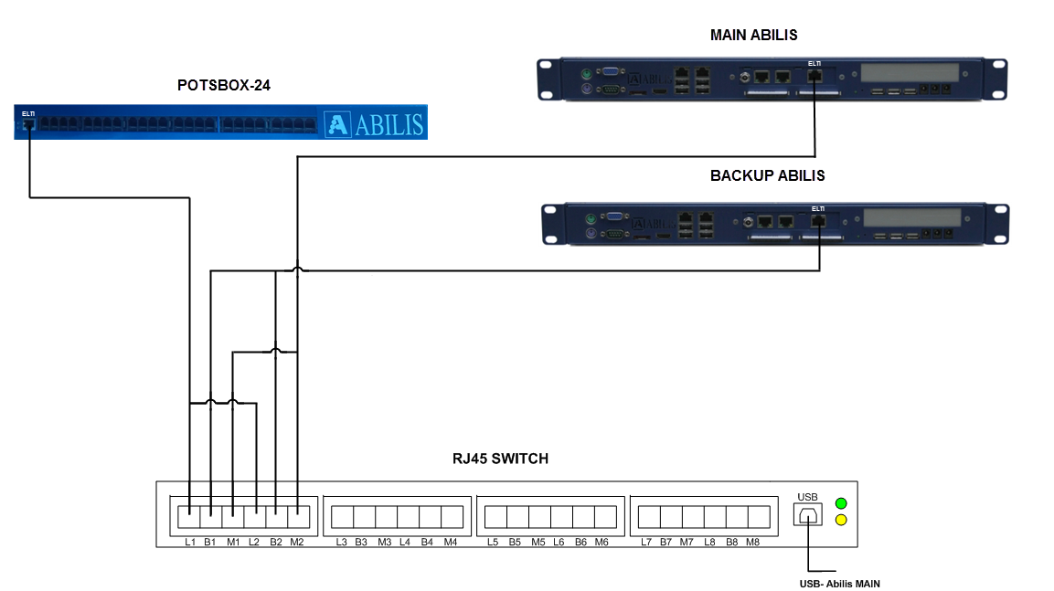
When Abilis MAIN is up, the ELTI line is connected to M1 and M2, so they're used by Abilis MAIN.
When Abilis MAIN us down, the ELTI line is switched to B1 and B2 and they're connected to Abilis BACKUP.
![[Note]](../images/note.png) | Note |
|---|---|
For POTSBOX is recommended to use a separate power supply, not from ABILIS. |
RJS can be used to switch 1GB lines. The 1GB port uses all 8 pins unlike the RJS, which uses only central pins 4,5 and 3,6 (remaining pins 1,2 and 7,8 are not connected). For this reason to switch a 1GB line will be required 2 RJS ports.
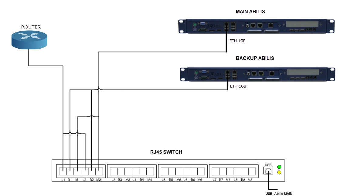
When Abilis MAIN is up, the 1GB line is connected to M1 and M2, so they're used by Abilis MAIN.
When Abilis MAIN us down, the 1GB line is switched to B1 and B2 and they're connected to Abilis BACKUP.
![[Tip]](../images/tip.png) | Tip |
|---|---|
Interesting chapters: |