Step-by-step instructions for connecting your Abilis to the internet, configuring your local network
and keeping it secure. Every task is done through the Web Interface at
Networking > Settings.
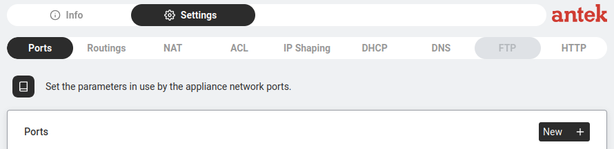
The Settings page has tabs across the top: Ports, Routings, NAT, ACL, IP Shaping, DHCP, DNS, FTP, HTTP.
Each How-To below tells you exactly which tab to use.
Understanding the subnet mask and /24
Goal: Read an address like 192.168.1.0/24 and know exactly which
addresses are on your network and which are not — before you set the LAN IP on the Abilis.
Why it matters: Two devices can only talk directly if they're on the same
subnet. Get the subnet mask wrong and devices that
share a cable still can't reach each other, or the Abilis hands out addresses no one can use.
An IP address has two parts: the network
part (which LAN you're on) and the host part (which device you are). The mask
is what splits them. Think of it like a street address — the mask decides how much is "the
street" and how much is "the house number." Everyone on the same street reaches each other
directly; to reach another street you go through the
gateway.
The /24 is just the mask written short (CIDR notation): it means
24 bits are the network part, leaving 8 bits for hosts. /24 is
the same as 255.255.255.0.
Worked example — 192.168.1.0/24:
Network part: the first three octets — 192.168.1. Every device on this LAN starts with 192.168.1.
Host part: the last octet — 8 bits, so 256 combinations (0–255).
192.168.1.0 is the network address (the "name" of the LAN — don't assign it to a device).
192.168.1.255 is the broadcast address (reaches everyone at once — also not assignable).
That leaves 192.168.1.1 to 192.168.1.254 — 254 usable addresses for the Abilis, PCs, phones and cameras.
So if you set the Abilis to 192.168.1.1/24, any device from .2 to
.254 with the same /24 mask can reach it directly. A device set to
192.168.2.50 cannot — different street.
The rule: the /n counts the network bits. A smaller host part
= fewer devices but more separate networks. /24 = 254 hosts; /25 = 126; /26 = 62. Pick the mask
that fits the device count you actually have.
Configure LAN settings (IP address, subnet, gateway)
Goal: Sets the IP address of the Abilis on your local network. This is the
address every device on your LAN uses to reach the Abilis — and through it, the internet,
phone system and everything else. Getting this right is the foundation of your entire setup.
Why it matters: If two devices share the same IP, neither works. If the Abilis
IP doesn't match what your devices expect, they can't reach it.
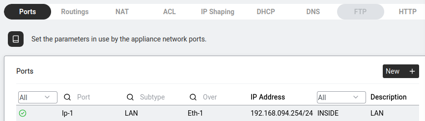
Go to Networking > Settings > Ports.
Settings > Ports — each row is a network interface.
You see a table of all network ports. Each row shows:
Status (green icon = active), Port (e.g. Ip-1),
Subtype (LAN, WAN…), Over (physical interface like Eth-1),
IP Address (e.g. 192.168.094.254/24) and Description.
Click on the LAN port row (typically Ip-1 with Subtype "LAN" over Eth-1).
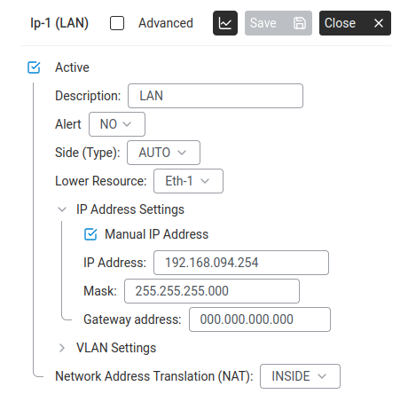
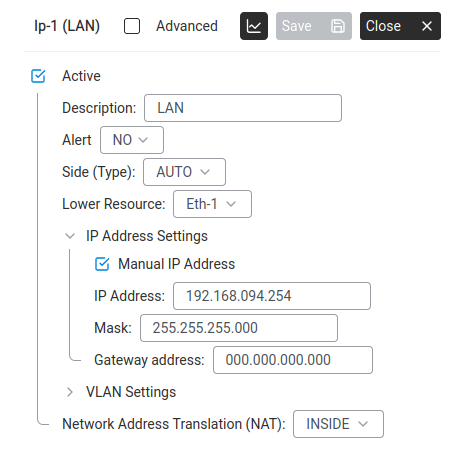
A detail panel opens. Key fields:
LAN port detail panel — IP address, mask, NAT zone.
Active — must be ticked for this port to work.
Description — a label for your reference (e.g. "LAN").
Alert — whether to notify you if this port goes down (NO by default).
Side (Type) — usually AUTO. Leave it unless instructed otherwise.
Lower Resource — the physical interface (e.g. Eth-1). Do not change this.
Expand IP Address Settings:
Tick Manual IP Address.
IP Address: the address you want (e.g. 192.168.1.1).
Mask: the subnet mask (e.g. 255.255.255.0 for a /24 network — the form accepts the standard or zero-padded form).
Gateway address: leave as 0.0.0.0 on a LAN port — the Abilis itself is the gateway for LAN devices.
Check the Network Address Translation (NAT) dropdown at the bottom — for a LAN port this must be INSIDE.
Click Save.
If you change the IP address you will lose your browser connection immediately.
Type the new address in your browser to reconnect. Write it down before clicking Save.
Advanced: CLI equivalent
The CLI command sequence for this task is documented in
Chapter 84.1 — How to configure LAN settings of the old Abilis manual.
A rewritten CLI guide is in preparation; this link will be updated when it is ready.
Goal: Gets your Abilis online using a mobile data connection (4G/LTE)
through an LTE-BOX or SIM dongle.
LTE-BOX — a mobile broadband modem built into or connected to the Abilis. Uses a SIM card
to connect to the cellular network. APN (Access Point Name) — a setting from your mobile
operator that tells the modem how to connect.
Disable the SIM's PIN code first. Most SIMs ship with PIN-protection
enabled. Either disable the PIN by inserting the SIM into a phone first and turning
SIM-lock off, or enter the PIN in the modem's settings — otherwise the modem will
silently fail to register and the connection will never come up.
Insert the SIM card into the LTE-BOX and connect it to the Abilis.
Go to Networking > Settings > Ports.
Settings > Ports — each row is a network interface.
Look for a port with Subtype "WAN" and Over "EthLte-1" or similar — this is your LTE modem.
Click on it. Check Active is ticked.
Set the APN to match your mobile operator. If you don't know it, call your operator or search "[operator name] APN settings."
Common Italian examples: internet (generic), mobile.vodafone.it, ibox.tim.it.
Connect to the internet via an Ethernet DSL modem (PPPoE)
Goal: Your ISP provided an ADSL or VDSL modem that plugs into the
Abilis over Ethernet, and the line requires a username and password. The Abilis
establishes a PPPoE session over the Ethernet link and uses the resulting connection
as the internet gateway.
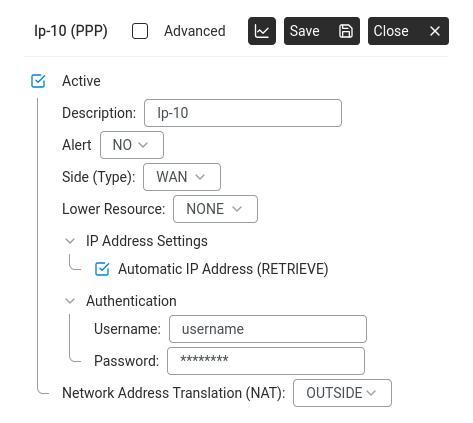
A PPPoE resource: Side (Type) set to WAN, Automatic IP Address (RETRIEVE), Authentication with username and password, NAT set to OUTSIDE.
PPPoE (Point-to-Point Protocol over Ethernet, RFC
2516) — a protocol that wraps an authenticated PPP session inside Ethernet frames.
It is the standard access method for most European xDSL operators.
Access Concentrator — the ISP-side equipment that terminates the
PPPoE session at the other end of the line.
Bridge mode — the modem hands raw Ethernet frames straight through
to the Abilis, which does the PPPoE login itself. Routed mode — the
modem terminates the line and acts as its own router (not what you want here).
CHAP / PAP — the two authentication methods PPP can use; CHAP
is challenge-based and more common, but the ISP picks which is required.
What you need from your ISP: the PPPoE username and password; whether
the public IP is dynamic (assigned during the PPP session — most common) or fixed;
whether the DSL link itself requires a VLAN tag (some operators do, most do not); and
the service name, if the ISP specifies one.
Prerequisite — modem in bridge mode: the DSL modem must be configured
by the ISP or by you as a transparent bridge. A modem in routed mode will
not allow the Abilis to initiate the PPPoE session. If the modem shipped pre-configured
in routed mode, factory-reset it and set bridge mode before going further. (The exact
procedure varies by modem — usually a small reset hole on the back held with a
paperclip for ten seconds, then a one-time login to the modem's own web interface to
switch from routed to bridge mode. Consult the modem's own quick-start guide if the
reset button isn't obvious.)
Connect the DSL modem's Ethernet output to a free Ethernet port on the Abilis
(for example Eth-2). Connect the telephone line to the modem and
wait until the modem's DSL-sync LED stops blinking.
If — and only if — your ISP requires a VLAN tag on the DSL link, prepare the
Ethernet port first. See Run several networks through one
Ethernet cable (VLANs) for the port-level VLAN setup; the PPPoE client you
create below will then use the tagged sub-interface. If the line is untagged
(the usual case), skip this step.
Go to Networking > Settings > Ports and click
New +. Create a new IP resource bound to the Ethernet port the
modem is plugged into — this is the resource that will carry the PPPoE session
and hold the ISP-assigned address.
On the new resource panel, set:
Description: a clear label, e.g. WAN_DSL.
Lower Resource: the Ethernet port the modem is connected to
(e.g. Eth-2).
Network Address Translation (NAT):OUTSIDE —
this is a WAN-side port.
Fill in the PPPoE credentials: the ISP-supplied username and password, authentication
mode (leave at the default — the ISP dictates CHAP or PAP), service name (blank
unless specified by the ISP) and IP-assignment mode (dynamic for most lines; enter
the reserved IP instead if the ISP has assigned a static public address).
Enable DNS learning so the Abilis picks up the ISP's resolvers through the PPP
session, and enable TCP MSS clamping on the connection. MSS clamping prevents the
well-known failure where some HTTPS sites will not load over a PPPoEWAN because
the PPP and Ethernet headers leave less room for TCP than the endpoints assume.
Click Save. The Abilis starts PPPoE discovery on the Ethernet
port; once the Access Concentrator responds and PPP authentication succeeds, the
resource comes up with its assigned address.
Add a default route through the new WAN — see Configure
the default IP route. Its gateway should be OUT-IP so the route
follows whichever address the ISP assigns on each session.
Verify on Networking > Info. The new WAN resource
should show a green status icon and the ISP-assigned address. Open a browser on
the LAN and load a public site to confirm internet is reachable.
If the session will not come up: the most common cause
is an incorrect username or password — check the boot log and SYSLOG output for PPP
authentication failures. Other common causes: a required VLAN tag has not been
configured on the Ethernet port; the modem is still in routed mode rather than bridge;
the ISP's service name is required but not set.
Ethernet-connected DSL modems used this way do not support
multiple VPI/VCI pairs or PPPoA/IPoA routed mode — those require a different modem type.
If your ISP requires either, contact Anteklab to
confirm which modem types your unit supports.
If a field name doesn't match exactly. The labels
inside the PPPoE-specific panels (subtype name, username/password inputs, IP/DNS
retrieval toggles, MSS clamping location) can vary slightly between firmware
releases. The concepts above are stable; if a field isn't named verbatim on your unit,
look for its semantic equivalent on the same panel.
Connect to the internet with a fixed public IP (static WAN)
Goal: Your ISP has assigned you a fixed public IP address on an Ethernet
DSL/fibre modem. There is no login — the Abilis just needs to sit on the WAN link with
the address you were given.
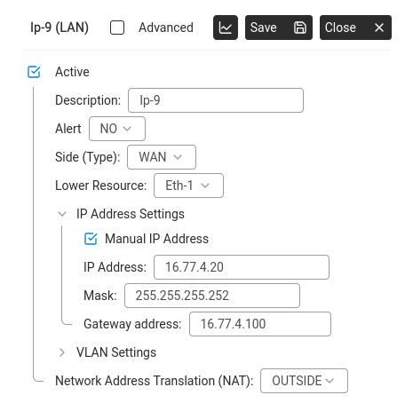
A static WAN resource: Manual IP Address ticked, IP/Mask/Gateway filled in, NAT set to OUTSIDE.
What you need: the public IP address and
subnet mask from your ISP, and the VLAN ID if the
operator requires tagging on the line.
Two cases — identify which one you're in before starting:
Bridged modem. The ISP equipment just passes Ethernet frames through;
the public IP and gateway belong to the Abilis port directly. Set the IP/mask on the
Abilis port as below; leave the Gateway field at the ISP-supplied next-hop.
Routed modem. The ISP equipment terminates the line itself and hands
the Abilis a private LAN-side address. You'll fill in step 7 (Gateway = the
modem's LAN-side IP) and the public IP lives on the modem, not on the Abilis.
Connect the modem to a free Ethernet port on the Abilis.
Go to Networking > Settings > Ports.
Click New +.
Resource: a free IP slot (e.g. Ip-3).
Subtype:LAN (IP over LAN — used for any Ethernet-based
connection, WAN or LAN).
Lower resource: the Ethernet port connected to the modem
(e.g. Eth-2).
Click Save.
On the IP resource panel, configure:
Tick Manual IP Address.
IP Address: the public IP your ISP gave you (e.g. 80.80.80.80).
Mask: the subnet mask (often 255.255.255.255 for a /32
point-to-point, or whatever the ISP specified). A /32 mask means the address
belongs to a single host with no surrounding subnet — common when the ISP gives
you one fixed public IP and places the upstream gateway outside the subnet.
(If required) VLAN ID: the tag number from the operator.
Click Save.
Add a default route through this line — see
Configure the default IP route. If the ISP's equipment is
a router rather than a bridged modem, also set the Gateway
field to the router's LAN-side IP.
Verify at Networking > Info — the port should go green.
Run several networks through one Ethernet cable (VLANs)
Goal: Carry two or more separate IP networks over the same physical
Ethernet cable — for example a management network and a guest network, or several
tagged networks coming from an upstream switch. Each network will appear on the Abilis
as its own IP resource with its own address, NAT side, firewall rules and traffic
statistics.
VLAN (Virtual LAN) — a logical network that shares
a physical Ethernet cable with other VLANs. Each VLAN is identified by a number
(1–4094) added to the Ethernet frame as a tag. Untagged
frames — traffic with no tag — belong to the default (native) VLAN.
How the Abilis represents VLANs: there is no dedicated VLAN page.
VLAN is a property of each IP resource, set inside the resource's configuration
panel. To carry three VLANs on one cable you create three IP resources, all pointing
at the same Ethernet port as their Lower Resource, each with a different VLAN ID.
Hardware requirement: the Ethernet port the cable plugs into must
support VLAN tagging. Gigabit NICs typically do; some older 100 Mbit/s ports do not.
If the port does not support tagging, the configuration will refuse to save — the
error tells you to try a different port.
Step 1 — Open the Ethernet port and enable multiple VLANs on it
By default an Ethernet port is configured to carry a single untagged network. To
carry tagged VLANs on top of that, the port's tag capacity has to be
raised first.
Tag capacity — the maximum number of tagged VLANs the port will
accept. Default is 0 (untagged traffic only). Set this to the number of tagged VLANs
you plan to carry on this cable, on top of the untagged native VLAN, not
including it.
Go to Networking > Settings > Ports.
Open the row for the Ethernet port you plan to share (e.g. Eth-2).
Its configuration panel opens on the right.
Tick Advanced at the top of the panel to reveal the full set of
fields, and raise the tag capacity to cover the number of tagged VLANs you intend
to carry on this port — for four tagged VLANs on top of the native one, four
is enough.
Click Save.
A system restart is required for the port to pick up the new tag
capacity. Plan the change for outside business hours, or before you start adding the
individual VLAN resources in Step 2 (those don't need a reboot themselves).
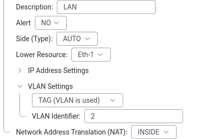
IP resource configuration panel. VLAN Settings is the collapsible section between IP Address Settings and NAT — expand it on each new resource to set that resource's VLAN ID.
Still on Networking > Settings > Ports, click
New +.
In the add-resource dialog, pick a free IP slot (e.g. Ip-3) and choose
the LAN subtype — the most common case, where the VLAN carries an
ordinary routed LAN segment.
Click Save. The new resource's configuration panel opens.
Set the basics:
Description: a clear label, e.g. Lan_voip,
Lan_guest, Lan_mgmt.
Lower Resource: the Ethernet port from Step 1 (e.g.
Eth-2). This binds the VLAN to that physical cable.
Expand IP Address Settings, tick Manual IP Address
and fill in the address and mask the Abilis will hold on this VLAN. Leave the
gateway at 0.0.0.0 on a LAN-side VLAN — the gateway is only set on a
WAN resource that has an upstream next-hop.
Expand VLAN Settings and enter the VLAN tag (the 1–4094 number
configured on the upstream switch). Leave the setting at its default only if this
resource is meant to carry the untagged (native) VLAN on the port.
INSIDE — LAN-side traffic; NAT will happen on the WAN resource
it eventually egresses through.
OUTSIDE — WAN-side segment (rare for a VLAN on a LAN-side cable).
NO — no NAT (for routed segments between trusted sites).
Click Save.
Repeat steps 1–8 for each additional VLAN on the same Ethernet port. All the new
resources share the same Lower Resource (Eth-2), each with its own
VLAN ID.
After saving, each VLAN appears as its own row in the Ports table with
its own status icon, address and statistics. The upstream switch or router port
connected to this cable must be configured as a trunk and must
tag traffic with the matching VLAN IDs — otherwise the Abilis receives frames
that do not match any of your tagged resources and they are dropped.
Field labels — verify against your unit. The exact
labels inside the VLAN Settings accordion and the advanced Ethernet-port
panel (the tag-capacity field in Step 1, the tag-value field in Step 2) may vary slightly
by GUI release. The concepts above — raise the port's tag capacity; then one IP resource
per VLAN sharing the Ethernet Lower Resource, each with its own tag — are stable.
Set up a guest network with limited internet access (worked example)
Goal: You want visitors — customers in a waiting room, contractors,
family members at home — to get internet without being on your business LAN.
Guests should reach the internet, nothing on your internal network and not be able to
saturate your line.
Office and guest devices run on separate VLANs through a managed switch. The Abilis has an IP on each VLAN and an ACL blocking traffic between them.Expand VLAN Settings on the guest resource. Set it to TAG and enter the VLAN Identifier your switch uses for the guest network.
This is a worked example that ties several how-tos together. Each step points at the
focused how-to for the detail.
Add a guest IP resource on a VLAN. Pick a VLAN tag not used
elsewhere (e.g. 100) and a fresh subnet for the guests
(e.g. 192.168.100.0/24). Follow
Run several networks through one Ethernet cable (VLANs) to
create the VLAN, and give the new resource a clear description like
Lan_guest. Set NAT zone to INSIDE.
Give the guest VLAN its own DHCP pool. On the new resource,
follow Set up the DHCP server. The pool comes from the
guest subnet automatically. For DNS: leave it as the Abilis (Ip-1) if you
want your DNS-filtering rules to apply to guests too; set it to an external
resolver (e.g. 8.8.8.8) if you'd rather guests bypass your filtering and
go straight to public DNS.
Deny source 192.168.100.0:192.168.100.255 → destination
the business LAN (e.g. 192.168.1.0:192.168.1.255). This blocks guests
from reaching any internal host.
Permit source 192.168.100.0:192.168.100.255 → destination
any. This allows them out to the internet.
The order matters: the deny rule must be evaluated first (lower priority number).
Cap the bandwidth. Follow
Cap bandwidth per IP address or subnet (IP Shaping) to
limit the whole guest subnet to, say, 30% of your WAN capacity. Guests stay usable
for web and video calls; they can't starve the business traffic.
(Optional) Block business-hours access. If the guest network should
only be live when the office is closed (or vice versa), add an ACL rule with a
time condition. This is supported directly in the ACL rule editor.
Plug the guest VLAN into the switch — either a dedicated port tagged with VLAN 100,
or a WiFi SSID that the access point maps to VLAN 100. From the guest's point of
view, this is an ordinary internet connection; they have no visibility into your
business network.
The same pattern scales to three, four or more isolated networks on the
same physical cable — a staffVLAN, a VoIP phonesVLAN, a camerasVLAN and a guestVLAN — each with its own subnet, DHCP range, bandwidth cap
and ACL posture. Build them one at a time and test each before adding the next.
Goal: Understand how the Abilis picks where to send each packet, so the
Routings table — and especially a backup default route —
behaves the way you expect.
Why it matters: When you add a second WAN line for failover, the Abilis
doesn't load-balance by accident or pick at random. It follows two simple tie-breakers.
Knowing them is the difference between a backup that takes over cleanly and one that
never activates.
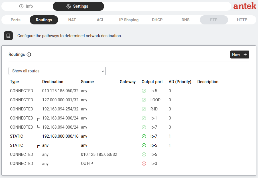
For every packet, the Abilis looks at the destination address and checks it against the
Routings table. Think of the table as a set of signposts, each covering a range of
addresses. The packet follows the most specific signpost that covers its
destination — the one with the longest matching prefix:
A route for 192.168.5.0/24 is more specific than one for 192.168.0.0/16.
The default route — destination any in the Web Interface,
written 0.0.0.0/0 in the reference manual — is the least specific of all.
It covers everything, so it is the signpost used only when nothing more
specific matches. That's why internet-bound traffic ends up there.
When two routes are equally specific, the Abilis breaks the tie with the
AD (Priority) column — the number the how-tos below call the
metric: the route with the lower value wins.
Both routes cover everything, so they tie on specificity. The AD breaks the tie:
1 wins, and all internet traffic uses the fibre. If the fibre goes down, its port is marked
down (the red status icon in the Routings table) and routes through it are ignored — the
only default route left is the LTE one (AD 180), and traffic shifts to it
automatically. When the fibre returns, its lower AD takes the traffic back.
The rule: most specific prefix first; between equally
specific routes, the lowest AD (metric) wins. Design failover by giving the preferred line
the lower AD.
Goal: Tells the Abilis where to send traffic that isn't destined for the local network.
Without a default route, the Abilis can talk to LAN devices but nothing beyond: no websites, no email, no VPN.
Analogy: Routing is like road signs. The default route is the sign that says
"for everything else, take this highway."
Go to Networking > Settings > Routings.
Routings table — default routes and their status.
Look for a route with destination any and gateway OUT-IP — that is the default route.
It tells the Abilis "for any traffic not going to a local network, send it out through this WAN port."
If it exists, verify the Output port column shows the correct WAN interface (e.g. Ip-5)
and the status icon is green.
If it doesn't exist, click New +:
Destination:any (meaning "all traffic not matched by a more specific route")
Source:any
Gateway:OUT-IP (the Abilis resolves this to the public address of the selected WAN port)
Output port: select the IP resource that connects to the internet
(e.g. Ip-5 for an FTTC line, or Ip-3 for a backup LTE modem)
Click Save.
Two default routes pointing to different output ports create automatic failover.
In the example above, Ip-5 (green) is the active primary route and Ip-3 (red) is the
backup that takes over if the primary goes down.
Advanced: CLI equivalent
The CLI command sequence for this task is documented in
Chapter 84.12 — How to configure the default IP route of the old Abilis manual.
A rewritten CLI guide is in preparation; this link will be updated when it is ready.
Add a backup default route (two WAN lines, automatic failover)
Goal: You have two WAN lines — a primary (e.g. fibre) and a backup
(e.g. a second DSL or LTE line) — and you want the Abilis to send all internet traffic
through the primary, and only switch to the backup if the primary fails.
How it works: you add a second default route with a higher
metric (the AD (Priority) column). The Abilis always prefers the route with the lowest metric.
The backup route stays dormant until the primary goes down, then takes over automatically,
then hands back when the primary recovers — How the Abilis chooses
a route explains why.
Make sure both WAN lines are configured and appear green in
Networking > Info.
Go to Networking > Settings > Routings.
Routings table — default routes and their metrics.
Confirm the existing default route (destination any) points to the
primary WAN port and note its metric (usually 1).
Click New + and add the backup default route:
Destination:any
Source:any
Gateway:OUT-IP
Output port: the backup WAN port (e.g. your LTE port).
Metric: a value much higher than the primary (e.g. 180). 180 is the conventional value for backup routes — high enough that the primary (typically AD 1) always wins, but otherwise arbitrary. Any value strictly larger than the primary's metric works.
Click Save. Both routes now appear in the table — the primary active,
the backup dormant.
To test failover, disconnect the primary WAN cable for a minute. The
Abilis should switch to the backup within seconds; reconnecting the primary returns
traffic to it automatically. For the LTE-specific variant, see
Set up LTE as a backup internet connection.
Goal: Makes the Abilis automatically hand out IP addresses to every device
that connects. Without DHCP you'd need to manually configure an IP on every computer, phone and printer.
DHCP (Dynamic Host Configuration Protocol) — automatically assigns IP addresses,
gateway and DNS information to devices when they connect.
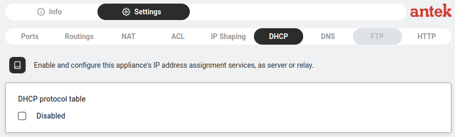
Go to Networking > Settings > DHCP.
On a fresh system you see "DHCP protocol table" with a Disabled checkbox. Click on it.
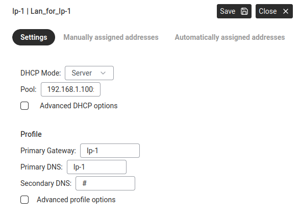
Pool:AUTO — the Abilis automatically calculates the address range
from the IP resource's subnet. For a LAN on 192.168.001.000/24, the pool
covers all available addresses in that subnet. You can also enter a specific starting address
if you need to limit the range.
Leave Advanced DHCP options unchecked unless you have specific needs.
Under Profile:
Primary Gateway:Ip-1 — tells devices "the Abilis is your gateway."
Primary DNS:Ip-1 — tells devices "use the Abilis for DNS" (enables caching and filtering).
Secondary DNS:# (none), or a fallback like 8.8.4.4.
Click Save.
Reserving a fixed address for a device
How DHCP works — the 4-step handshake between device and server.
Devices like printers or cameras should always have the same IP. Use manual assignment instead of configuring a static IP on the device itself.
In the DHCP dialog, go to the Manually assigned addresses tab.
Enter the device's MAC address and the IP address you want to reserve.
Click Save.
The Automatically assigned addresses tab shows every device that received
an address from the pool — the quickest way to see "what's connected right now."
Advanced: CLI equivalent
The CLI command sequence for this task is documented in
Chapter 84.23 — How to activate the DHCP resource of the old Abilis manual.
A rewritten CLI guide is in preparation; this link will be updated when it is ready.
Forward DHCP requests to an existing DHCP server (relay mode)
Goal: You already have a DHCP server somewhere on your network
(a Windows server, a central appliance, a different router) and you want the Abilis to
pass DHCP requests from its LAN through to that server instead of answering them
itself. The server keeps control of address assignments; the Abilis just passes messages
back and forth.
Why use it: centralised control of addresses across many sites, or
reservations configured on an existing corporate DHCP server that the Abilis shouldn't
override.
This is an enterprise / multi-site pattern. If your office has just one
Abilis and one network, you almost certainly want plain Server mode (the previous
how-to). Use Relay only when there is an upstream DHCP server you must
hand off to.
Note the IP address of the existing DHCP server (for example
192.168.1.250) — you will enter it in step 5.
Go to Networking > Settings > DHCP.
If DHCP is disabled, click the Disabled checkbox to enable it.
The DHCP configuration dialog opens.
DHCP tab — click to enable and open the configuration dialog.
In the DHCP Server field, enter the IP address of your existing
DHCP server.
Click Save.
Test — connect a computer to the Abilis LAN. It should receive an address from the
upstream DHCP server, not from the Abilis itself. In
Networking > Info you can check the DHCP log to see the
relayed requests.
In relay mode the Abilis does not hand out addresses on its
own. If the upstream DHCP server is unreachable, LAN clients cannot obtain an address and
your network will stop working for new devices. Make sure the link to the DHCP server is
reliable before switching from server mode to relay mode.
The three kinds of NAT (and which one the Abilis uses)
Goal: Know the difference between the NAT types textbooks and other
routers talk about, so the Abilis's INSIDE / OUTSIDE zones — and the
PAT switch — make sense.
Why it matters: "NAT" is one word for three different jobs. Knowing
which one you need tells you whether you're sharing one internet line, publishing a server,
or both.
NAT rewrites the addresses on traffic as it crosses the router. Think of the
Abilis as a mail room: outgoing letters get the office's return address stamped on them, and
replies come back to the mail room, which sorts them to the right desk inside.
There are three variants:
Static NAT — one inside address maps to one outside address, permanently.
Used to publish a single internal server under a fixed public address.
Dynamic NAT — a pool of inside addresses borrows from a pool of public
addresses, one at a time. Rare today; needs as many public addresses as simultaneous users.
PAT (NAT overload) — many inside addresses share one public address,
kept apart by port number. This is how a whole office shares a single internet
connection — the common case.
Worked example — one public IP, two PCs browsing: PC A
(192.168.1.50) and PC B (192.168.1.60) each open a website. The
Abilis rewrites A's request to leave as OUT-IP port 50001, and
B's as OUT-IP port 50002. The reply addressed to port
50001 is sorted back to A, the one to 50002 back to B. One public
address, connections told apart by port — that is PAT.
On the Abilis: the INSIDE zone is your LAN
(the addresses that get translated), the OUTSIDE zone is the WAN
(the public side). The default source-NAT rule (PR 1 on the NAT tab) is
PAT: everything from INSIDE leaves through the WAN's one public address,
each connection on its own port. Port forwarding is how you add
static-NAT behaviour for a specific service, so the outside can reach one server inside.
The rule: sharing one line out = PAT (already on by
default); letting the outside reach one service in = a port-forward (a static
mapping). You rarely need dynamic NAT.
Goal: Lets all devices on your LAN share a single internet connection.
Without NAT, only the Abilis itself could access the internet.
How it works: When your PC requests a webpage, the Abilis rewrites the request so it appears
to come from its own public IP. When the reply arrives, the Abilis forwards it back to your PC.
The outside world only ever sees the Abilis's address.
Source NAT — rewrites the sender's address on outgoing traffic.
Destination NAT — rewrites the receiver's address on incoming traffic (port forwarding).
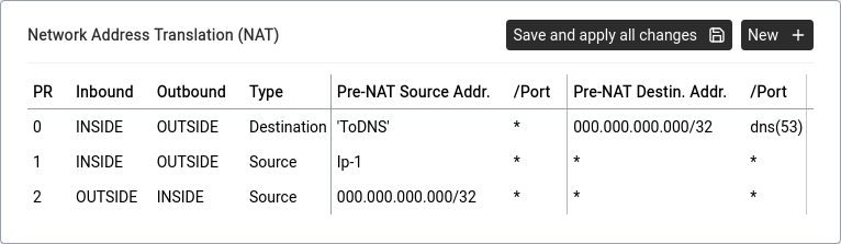
The NAT table at Networking > Settings > NAT has these columns:
Rules are checked in number order, starting from the smallest.
The Abilis reads the PR column top-down (0, then 1, then 2…) and
uses the first rule that matches the traffic. Anything below it is ignored.
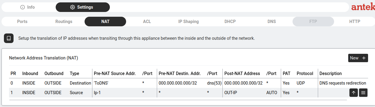
NAT table — two rules: DNS redirect and Source NAT for internet sharing.
Column
Meaning
PR
Priority — rules are processed lowest number first.
Whether this rule rewrites port numbers as well as addresses — see The three kinds of NAT above.
Protocol
Which protocol this rule applies to (* = all, UDP, TCP…).
Typical setup: two rules
#
Type
Purpose
0
Destination
DNS Redirect — intercepts all DNS traffic (port 53) and sends it to the Abilis DNS service. Makes DNS filtering work and ensures caching even if a device has a different DNS configured.
1
Source
Internet sharing — rewrites the source of all outgoing LAN traffic to the Abilis's public IP (OUT-IP). This is what actually gives your devices internet access.
This example creates rule #1 from the default setup — the rule that gives all LAN devices internet access.
About address fields. In NAT (and ACL) address fields you can type a literal IP/range,
or a resource name like Ip-1 — Abilis expands a resource name to "any address
that resource owns." Cleaner than typing the subnet, and self-updating if the subnet changes.
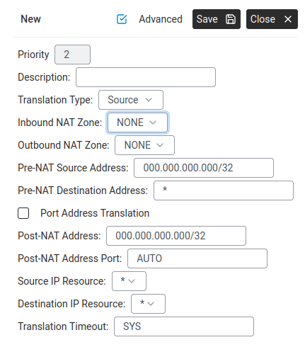
New NAT rule dialog — all the fields for a Source NAT rule.How NAT works — translating addresses between Inside and Outside zones.
Go to Networking > Settings > NAT, click New +.
Fill in:
Priority:1 (after the DNS redirect rule at priority 0)
The finished NAT table should show two rules: rule 0 (Destination — DNS redirect through the Abilis)
and rule 1 (Source — internet sharing via OUT-IP). Both use INSIDE → OUTSIDE zones.
NAT rules are powerful but easy to misconfigure. Follow the examples above carefully
and always test internet access immediately after saving. If you lose connectivity, the
issue is almost always a wrong zone (INSIDE/OUTSIDE) or a missing Source NAT rule.
If the unit becomes unreachable, connect a computer directly to a LAN port (bypassing any
switch) and revert the change from there.
Apply NAT (or a firewall rule) to a list of addresses
Goal: Instead of writing a separate NAT or ACL rule for each subnet or
host, define the group of addresses once as a List, then have
one rule reference the list. When the list changes, every rule that uses it updates
automatically.
Typical use cases: "NAT only the corporate LAN, not the guest VLAN";
"block all traffic from this known-bad set of IPs"; "allow SSH only from the office
subnets". In each case the rule stays tidy and the list can be edited on its own.
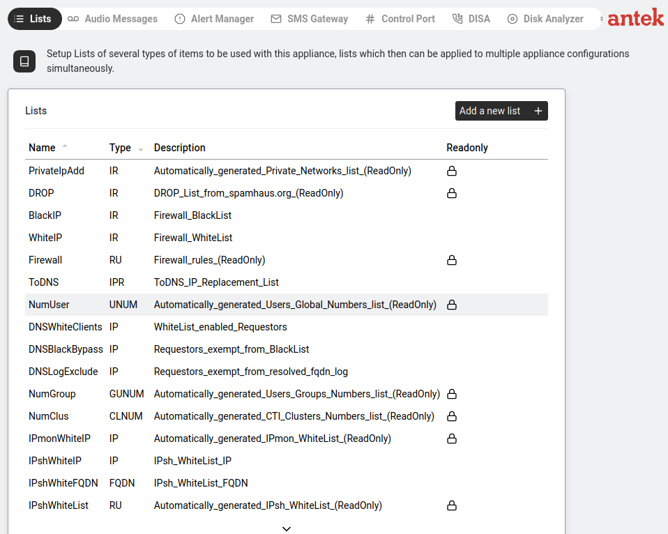
Create the list. Go to Tools > Lists.
Tools > Lists — the place to define named groups of addresses.
Click Add a new list + and fill in:
Name: a short identifier (e.g. corp_hosts).
Type:TUPR — the type for lists of IP
addresses or subnets used in NAT/ACL rules. (Other list types exist for user numbers,
ports, etc. — full taxonomy on Tools → Lists.)
Description: short reminder of what the list contains.
Click Save, then open the new list and add the entries — one line
per IP, range or subnet (e.g. 192.168.1.0/24).
Now reference the list in a NAT rule. Go to
Networking > Settings > NAT and click New +.
In the source or destination address field, instead of typing a single IP, pick the
list you just created (entry format list:corp_hosts).
Fill in the rest of the NAT rule as normal — translation type, post-NAT address,
direction — and click Save.
The same pattern works in ACL firewall rules, in
DNS filtering and anywhere else the GUI
accepts a list reference. To add or remove addresses later, edit the list only — every
rule that uses it picks up the change.
Open a port to reach an internal device from outside (port forwarding)
Port forwarding — external port mapped to an internal device.
Goal: Makes a device on your LAN accessible from the internet.
Example: your camera at 192.168.1.50:80 becomes reachable at
your-public-ip:8080.
Why 8080 externally instead of 80? Two reasons:
(1) port 80 on the Abilis itself is taken by its own web interface, so a port forward can't
grab it; (2) using a non-standard external port noticeably reduces drive-by attacks —
most automated scanners only probe well-known ports.
Go to Networking > Settings > NAT, click New +.
Set Translation Type:Destination.
Tick Port Address Translation.
Set Pre-NAT Destination Address Port: the external port (e.g. 8080).
Set Post-NAT Address: the internal device IP (e.g. 192.168.1.50).
Set Post-NAT Address Port: the internal port (e.g. 80).
Click Save.
Only forward ports to password-protected devices. Never expose management interfaces without proper security.
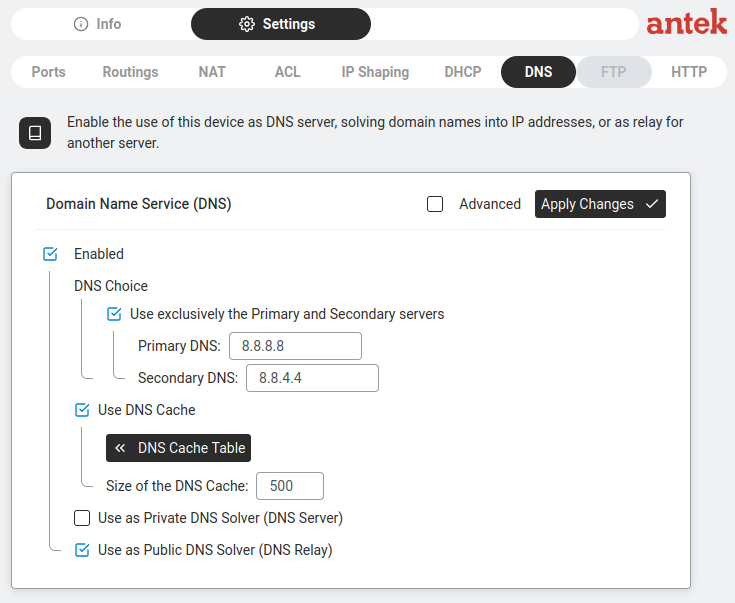
Goal: Controls how the Abilis resolves domain names into IP addresses.
The Abilis can act as a DNS server for your whole network, caching results and enabling filtering.
Two confusing labels on this page.Public DNS Solver (DNS Relay) means "answer DNS queries from LAN devices,
relaying upstream when needed" — almost always tick this.
Private DNS Solver (DNS Server) means "store your own local records like
printer.office" — only tick this if you have local-only names to publish.
Despite the names, neither setting exposes anything to the public internet.
Go to Networking > Settings > DNS.
Make sure Enabled is ticked.
Under DNS Choice:
DNS settings — Primary 8.8.8.8, Secondary 8.8.4.4, DNS Relay enabled.
Tick "Use exclusively the Primary and Secondary servers" (recommended).
Primary DNS: e.g. 8.8.8.8 (Google) or your ISP's DNS or a local server.
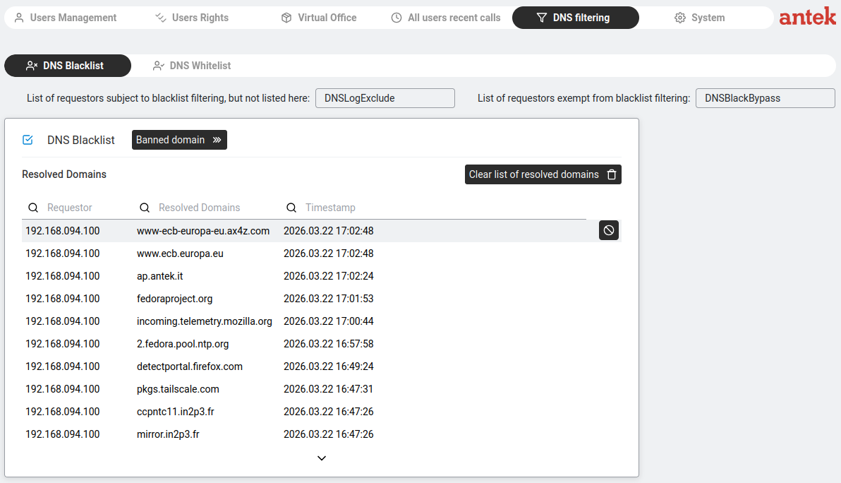
Goal: Prevents devices from accessing specific websites by blocking them at the DNS level.
When a device tries to visit a banned domain, the Abilis refuses to resolve the name.
DNS filtering — the Abilis checks each DNS request against a blocklist.
How it actually works: This is not a simple category checkbox system. It's a blacklist/whitelist
system that you manage through domain lists.
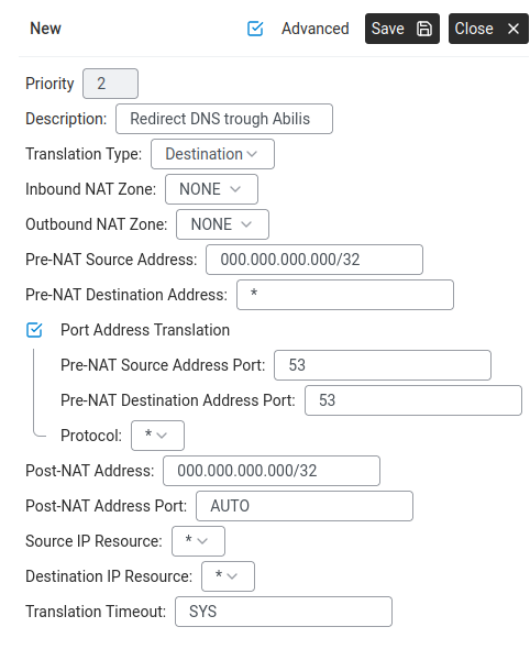
Goal: Forces every DNS request on your network through the Abilis,
even from devices with a different DNS configured (like 8.8.8.8).
Without this rule, a device can bypass your DNS filtering simply by using Google DNS.
Without the redirect rule, a device with its own DNS (e.g. 8.8.8.8) bypasses Abilis filtering. With the rule, the NAT rewrites the destination of any port-53 traffic back to the Abilis, so every device is filtered — whether it wants to be or not.
Go to Networking > Settings > NAT.
Check if a DNS redirect rule already exists (look for a Destination rule with port 53 and 'ToDNS').
If not, click New +:
Description:Redirect DNS through Abilis
DNS Redirect NAT rule — Destination type, port 53.
Give this rule a lower priority number than the Source NAT rule
so DNS traffic is redirected before it gets sent to the internet.
Advanced: CLI equivalent
The CLI command sequence for this task is documented in
Chapter 84.17 — How to redirect DNS requests to Abilis of the old Abilis manual.
A rewritten CLI guide is in preparation; this link will be updated when it is ready.
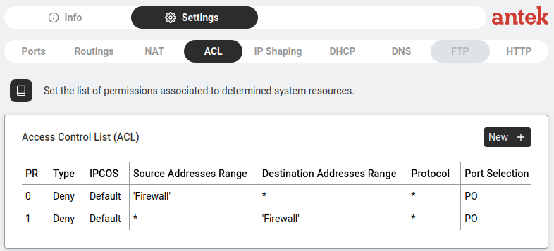
How firewall rules match — and what happens when nothing matches
Goal: Write firewall (ACL) rules that match the addresses you
intend, and understand the Abilis's default behaviour — which is the opposite of the
Cisco default you may have read about.
Why it matters: Two things trip people up. First, the Abilis writes address
matches differently from Cisco routers. Second, the Abilis lets unmatched traffic
through by default, where a Cisco ACL blocks it. Assume the wrong one and
you either lock yourself out or leave a hole open.
Matching addresses. A firewall rule needs to say "these addresses." The
Source / Destination Addresses Range fields take four plain forms:
a single address — 192.168.1.50
an explicit range — 10.0.0.1:10.0.0.50
a named list in quotes — 'Firewall' (managed at Tools > Lists)
* or any — everything.
To match a whole subnet, write it as a range: 192.168.1.0:192.168.1.255 covers all
of 192.168.1.x — the network that
subnet-mask notation would call 192.168.1.0/24.
Slash notation itself is not accepted here: type 192.168.1.0/24 into an
address field and it turns red with a validation error and Save greys out. (The
NAT address fields, by contrast, do take /24-style
values.) Saved addresses are redisplayed with zero-padded octets —
192.168.1.50 becomes 192.168.001.050; that's cosmetic.
If you come from the Cisco world, these forms replace the
wildcard mask — Cisco's inverted netmask where
0 means "this part must match" and 255 means "don't care." The
translation:
Cisco wildcard
Means
Abilis equivalent
192.168.1.50 0.0.0.0
exactly one host
192.168.1.50
192.168.1.0 0.0.0.255
the whole /24 network
192.168.1.0:192.168.1.255
192.168.1.0 0.0.0.15
a block of 16
192.168.1.0:192.168.1.15
0.0.0.0 255.255.255.255
any address
* / any
The implicit-deny difference — read this carefully. Rules are evaluated in
priority order and the first match wins (the next section covers this in detail). The
question is what happens to a packet that matches nothing. On a Cisco router, an
ACL ends with an invisible deny everything: anything you didn't explicitly
permit is dropped. The Abilis firewall does not do this. A packet that matches
no rule is routed normally. The built-in rules (PR 0 and PR 1 — read-only) only
deny the addresses on the 'Firewall' blacklist; everything else passes.
So the Abilis is allow-by-default (a blacklist), where Cisco is
deny-by-default (a whitelist).
Worked example — block one PC from the internet, allow the rest: because
unmatched traffic is allowed, one deny rule is all you need — no "permit the rest" rule:
PR
Type
Source
Destination
Protocol
2
Deny
192.168.1.50
any
*
(PR 2 because 0 and 1 are taken by the built-in read-only rules — your own rules start
at 2.) If instead you want the strict Cisco-style "deny everything except what I list,"
add your Permit rules first and finish with a Deny any any
rule at the highest PR number, so it is evaluated last — it replaces the implicit deny the
Abilis doesn't supply.
The rule: match addresses with a single IP, a range or a
named list (not a wildcard mask); and remember the
Abilis permits unmatched traffic — add a final Deny any any if you
want whitelist behaviour.
Goal: Controls which traffic is allowed and which is blocked.
Rules are checked top to bottom by Priority number — first match wins.
Lists — ACL rules can reference named Lists (from Tools > Lists)
instead of individual addresses, making management much easier.
List-reference syntax. List names go in single quotes
— 'blackip', 'Firewall'. The quotes tell Abilis "this is a
named list, not a literal IP." Without the quotes the value is parsed as an address and
the rule fails to save.
Rules are checked in number order, starting from the smallest.
The Abilis reads the PR column top-down (0, then 1, then 2…) and
uses the first rule that matches the traffic. The rest are ignored. So a specific permit
exception must have a smaller PR than the broader deny rule, or it will never be reached.
IP addresses, ranges or list names in quotes (e.g. 'Firewall', 'blackip').
Protocol
* = all protocols.
Port Selection
PO = match either the source or the destination port; SPO,DPO = match source and destination ports separately. Can reference a port list.
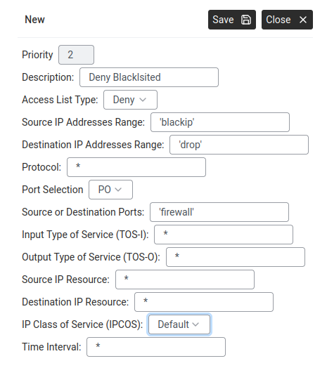
Adding a rule
New ACL rule — Deny Blacklisted using list references.How ACL rules are evaluated — top to bottom, first match wins.
Go to Networking > Settings > ACL, click New +.
Fill in:
Priority: lower = checked first.
Description: e.g. "Deny Blacklisted".
Access List Type: Deny or Permit.
Source IP Addresses Range: an IP, range or list name in quotes (e.g. 'blackip').
Destination IP Addresses Range: same format (e.g. 'drop').
Protocol:* for all, or TCP/UDP/ICMP.
Port Selection:PO to match either the source or the
destination port; SPO,DPO to match them separately (the form then shows
a Source Ports and a Destination Ports field).
Source or Destination Ports: a port list name (e.g. 'firewall').
Input / Output Type of Service (TOS-I, TOS-O): leave at *.
TOS-I matches the packet's incoming ToS byte (* = any value);
TOS-O rewrites it on the way out (* = don't change).
Source / Destination IP Resource: leave at *, or restrict
the rule to a specific IP resource (e.g. Ip-1) or a named list in quotes.
IP Class of Service: Default.
Time Interval:* = always. Can schedule rules for specific hours.
Click Save.
The power of Abilis ACL is Lists. Create one list called 'blackip' with 50 addresses
at Tools > Lists, then one ACL rule referencing 'blackip'. Much easier than 50 separate rules.
A wrong Deny rule can lock you out. Test immediately. If you do lock yourself
out, connect a computer directly to a LAN port on the Abilis (bypassing any switch, router,
or VLAN), set its address to the same subnet and revert the rule from there.
Block traffic between two internal subnets
Goal: Two internal networks are both attached to the Abilis — for
example, an office LAN and a separate CCTV-cameras subnet, or a production network and
a management network. They should reach the internet, but they should not
reach each other. A compromised camera must not be able to scan the office.
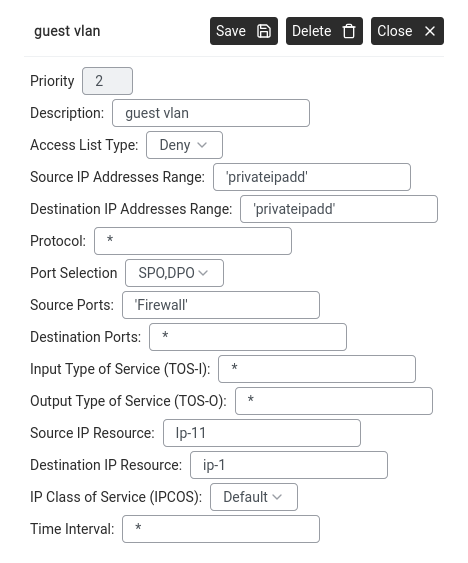
One ACL Deny rule blocks traffic between the two subnets while both share the same internet connection.An ACL rule with Access List Type set to Deny. Source and Destination IP Addresses Range are set to the two private subnets that should not reach each other.
Unlike NAT or firewall-to-WAN rules, this is strictly internal — LAN-to-LAN isolation
enforced by the Abilis's ACL as it routes between the two subnets.
Confirm both subnets are configured — each with its own IP resource and LAN setup.
See Configure LAN settings for each side.
Go to Networking > Settings > ACL.
Click New + and add the deny rule:
Priority: a low number, so the rule is evaluated before any
general permit. (Remember: lower number = higher priority on the Abilis —
PR 0 wins over PR 100.)
Action:deny.
Source: subnet A (e.g. 192.168.10.0:192.168.10.255 — the office).
Destination: subnet B (e.g. 192.168.20.0:192.168.20.255 — cameras).
Protocol:any.
Description:Block office → cameras.
If the block needs to be bidirectional (cameras also can't reach office), add a
second rule mirroring source and destination.
Test — from a host on subnet A, try to ping a device on subnet B. It should fail.
Internet access from both sides should still work (no NAT rules were changed).
If you also want selective access — e.g. allow office hosts to
reach one specific camera on the cameras subnet but nothing else — add a
permit rule for that exact source-destination pair at a higher
priority than the deny rule. First-match wins, so the more specific permit fires before
the broad deny.
Send specific traffic down a specific line (Policy-Based Routing)
Goal: You have two WAN lines and want certain traffic to
always go out through a specific one — for example, all VoIP traffic through the fibre
line (low latency), everything else through the LTE backup. Normal routing only looks at
the destination; policy-based routing can decide based on source, protocol and ports.
A routing rule with a protocol filter forces VoIP down the fibre for quality while browsing and email can use whichever line is available.
Policy-Based Routing (PBR) — a feature that overrides
the normal routing table based on rules about the traffic itself (who sent it, what
protocol, what ports). On the Abilis, PBR isn't a separate page or feature — it's
a side-effect of the ACL editor. You write an ACL rule with action permitand fill in the Output resource field. That combination
tells the Abilis: "let this traffic through, AND send it out via that specific port." A
regular deny rule (no output resource) just drops the traffic; a regular
permit rule (no output) lets it route normally.
Identify the traffic you want to redirect — for example: LAN host
192.168.1.50, UDP, destination port 5060 (SIP).
Identify the WAN line you want that traffic to use — for example Ip-5
(fibre).
Go to Networking > Settings > ACL.
ACL — new rule with source, destination, protocol and output resource.
Click New +. Configure:
Action:permit (PBR rules permit and redirect —
a deny rule just blocks).
Priority: a number that places this rule above any general
permit-all rules.
Protocol / Ports: e.g. UDP 5060 for SIP, UDP 10000–20000 for RTP,
TCP 443 for HTTPS.
Output resource: the WAN port the matching traffic should leave
through (e.g. Ip-5).
Click Save. ACL rules take effect immediately — no restart needed.
Test — send traffic that matches the rule. You can confirm the path it takes at
Networking > Info by watching the Line Load on the
chosen output port. If you have it, Tools > IP Flow Tracer
shows the exact route each packet follows.
ACL rules are evaluated in order of priority. If you already have a
broad permit any rule at priority 1, your PBR rule must sit at a higher priority
(lower number) to be matched first.
Set up a VPN tunnel between two Abilis devices (AIPT2)
VPN tunnel — two sites connected securely through the internet.
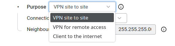
Goal: Creates a secure encrypted connection between two Abilis units.
Devices at both sites can communicate directly across the internet — as if connected by a
virtual cable.
AIPT2 (Abilis IP Tunnel version 2) — the current Abilis VPN protocol,
optimised for data and voice with improved encryption and performance over the original AIPT.
A tunnel can have up to 6 paths configured. Normally one path carries the traffic; backup
paths stay on standby and activate when the primary degrades or the bandwidth-on-demand
feature kicks in.
A tunnel always has two sides: one Abilis acts as the server, the other as the client.
Both sides must be configured with matching parameters. Below is the full walkthrough.
Which side is server, which is client? Pick whichever side has the more
stable public IP as the server — the client connects out to it. If one site
is behind a dynamic IP or CGNAT, that side should be the client. If both sides have stable
public IPs, the choice is arbitrary.
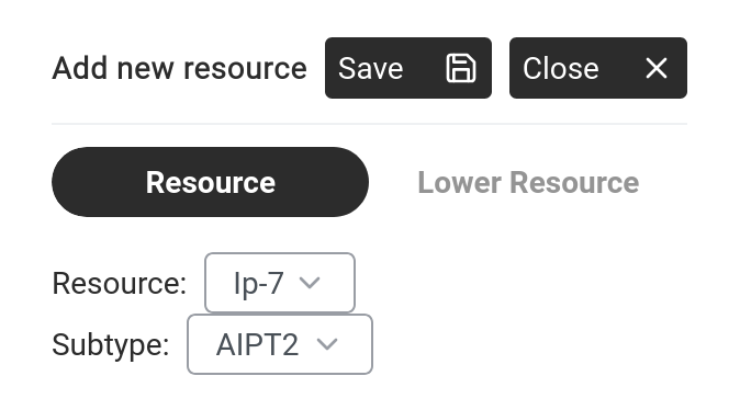
Networking > Settings > Ports — click New + to add a resource.
Click New +. The "Add new resource" dialog opens.
Add new resource — select an IP resource and set Subtype to AIPT2.
Set:
Resource: select an available IP resource (e.g. Ip-8).
Subtype:AIPT2.
Click Save. The tunnel configuration panel opens.
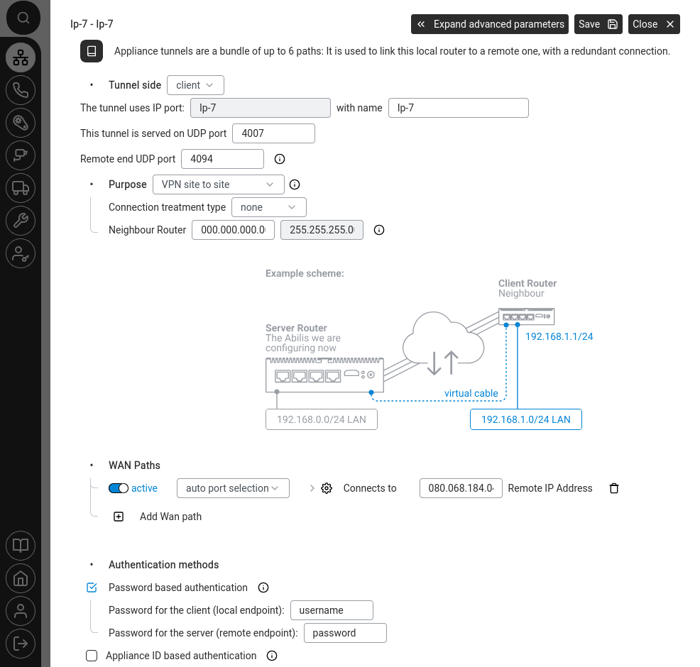
Step 2 — Configure the tunnel
AIPT2 tunnel configuration — all main settings with the example network diagram.
The configuration panel has these sections:
Tunnel identity
Field
What to set
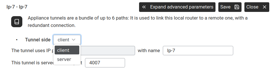
Tunnel side
client or server. One Abilis must be the server, the other the client.
Tunnel side — choose client or server.
The tunnel uses IP port / name
The IP resource name (e.g. Ip-8) that binds this tunnel to a port slot on this Abilis. Auto-filled from the resource you created in Step 1; you don't change it here.
This tunnel listens on UDP port
Default: 4008. Must match on both sides.
Remote end UDP port
# means same as local. Set a specific port if the remote side uses a different one.
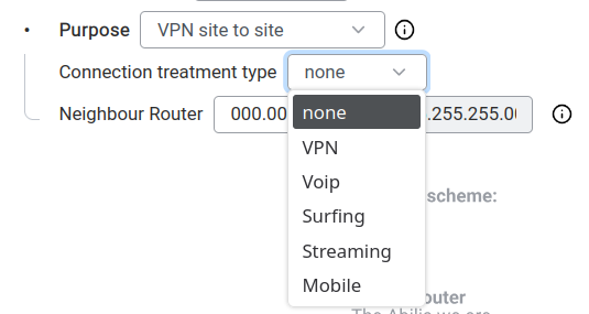
Mobile connections — handles variable link quality.
Neighbour Router — the IP address and subnet mask of the remote Abilis's LAN.
(Despite the field name, this is the remote LAN's network address, not a router on the link.) Use the
remote site's LAN subnet — in the example diagram: the server has LAN192.168.0.0/24,
the client has LAN192.168.1.0/24.
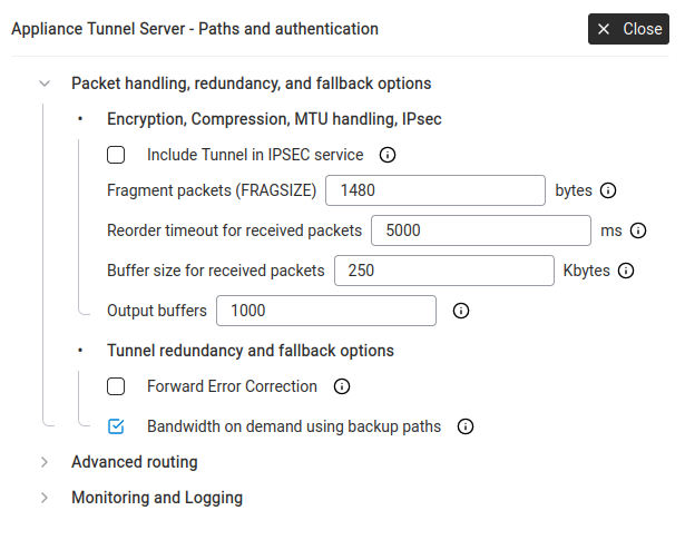
Maximum packet size before fragmentation. 1480 is the standard 1500-byte Ethernet MTU minus typical tunnel overhead. Lower the value if you see packet loss on the tunnel; raising it usually doesn't help.
Reorder timeout
5000 ms
How long to wait for out-of-order packets before giving up.
Buffer size for received packets
250 KB
Receive buffer. Increase for high-throughput tunnels.
Output buffers
1000
Transmit queue depth.
Forward Error Correction
☐
Adds redundant data so the receiver can recover lost packets without retransmission. Costs bandwidth, improves reliability.
Bandwidth on demand using backup paths
☑
When ticked, backup paths join the active path during congestion to add capacity (essentially load-balancing under pressure). When unticked, backup paths only activate on primary failure (traditional standby behaviour).
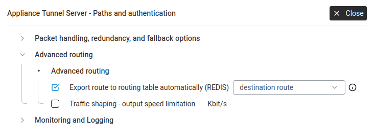
Advanced routing
Advanced routing — automatic route export and traffic shaping.
Export route to routing table automatically (REDIS) — when ticked, the Abilis automatically
adds a route to the remote LAN through this tunnel. Set to destination route so
traffic to the remote subnet is sent through the tunnel without manual routing rules.
Traffic shaping — output speed limitation — cap the tunnel's bandwidth (in Kbit/s).
Useful if you want to reserve bandwidth for other services.
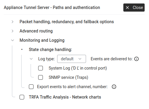
Monitoring and Logging
Monitoring and Logging — alerts, logging and traffic analysis for the tunnel.
State change handling — what happens when the tunnel goes up or down:
System Log — write to the control port log.
SNMP service (Traps) — send an SNMP trap (an unsolicited "something happened" message) to a monitoring system that's been configured to receive them.
Export events to alert channel — trigger an alert (SMS, email, call, digital output)
when the tunnel changes state. Select the channel number from
Tools > Alert Manager.
TRFA Traffic Analysis — Network charts — enable traffic statistics for this tunnel,
visible in Phone > Statistics. (Yes, network traffic data lives in the
Phone section — historical reasons; the page covers all traffic, not just calls.)
Step 4 — Save and verify
Click Save to apply the configuration.
Repeat the same process on the remote Abilis, setting it as the opposite side
(if this one is client, the remote must be server).
The UDP port, authentication and neighbour settings must match.
The VPN matrix shows colour-coded quality bars for each tunnel across time windows
(5 sec, 1 min, 15 min, 1 hour).
Colours: green = healthy, yellow = fair, orange = degraded, red = almost unusable, black = down, grey = inactive. (Same scheme as the VPN Connections matrix on the Info tab.)
Click a connection name to see Line Load (bandwidth graph) and Top 5 (who's using it).
If the tunnel stays red or black after configuration, verify that the remote Abilis
is reachable on the specified UDP port (default 4008), that the authentication method and credentials match
on both sides and that any firewalls between the two sites allow UDP traffic on that port.
Also check Networking > Info on both units to confirm WAN connectivity is healthy.
Goal: You have two WAN lines at each site, and you want your AIPT2VPN
tunnel to keep working even if one of the WAN lines fails. The tunnel uses both paths
for resilience — if the primary drops, traffic carries on over the backup without the
call or session breaking.
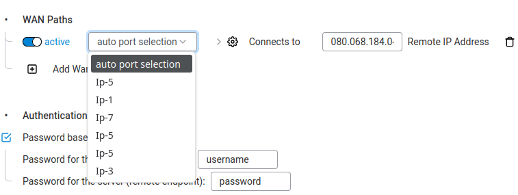
WAN Paths — where extra tunnel paths are added for redundancy.
Click Add Wan path. A new row appears.
Port: select the secondWAN interface (e.g. the LTE
port, Ip-7). The first row should already point at the primary
WAN.
Connects to → Remote IP Address: the public IP the remote Abilis
uses on its second WAN line. If auto-discovery is in use, leave
#.
Expand advanced parameters (top right). Under
Packet handling, redundancy and fallback:
Confirm Bandwidth on demand using backup paths is ticked — the
tunnel will activate the second path automatically when the primary cannot
carry all the traffic or goes down.
For lines of similar speed you can also tick Forward Error Correction
(FEC) to reduce packet loss on unstable links. FEC sends a small amount of
controlled redundant data with every transmission, so the receiver can
reconstruct lost packets without waiting for a retransmission. Worth the
bandwidth cost for voice, remote-control signalling and any flow where
retransmission delays would break the experience.
Click Save.
Repeat on the second Abilis — add its own second WAN path with the matching remote
IP from the first Abilis. The two configurations mirror each other.
Verify at Networking > Info > VPN Connections — both
paths should show traffic under the tunnel entry.
Pair this with alerting. In the tunnel's Monitoring and Logging
advanced panel, tick Export events to alert channel so you get an SMS or
email when the tunnel switches paths — useful if a WAN line has been down for a while
without anyone noticing.
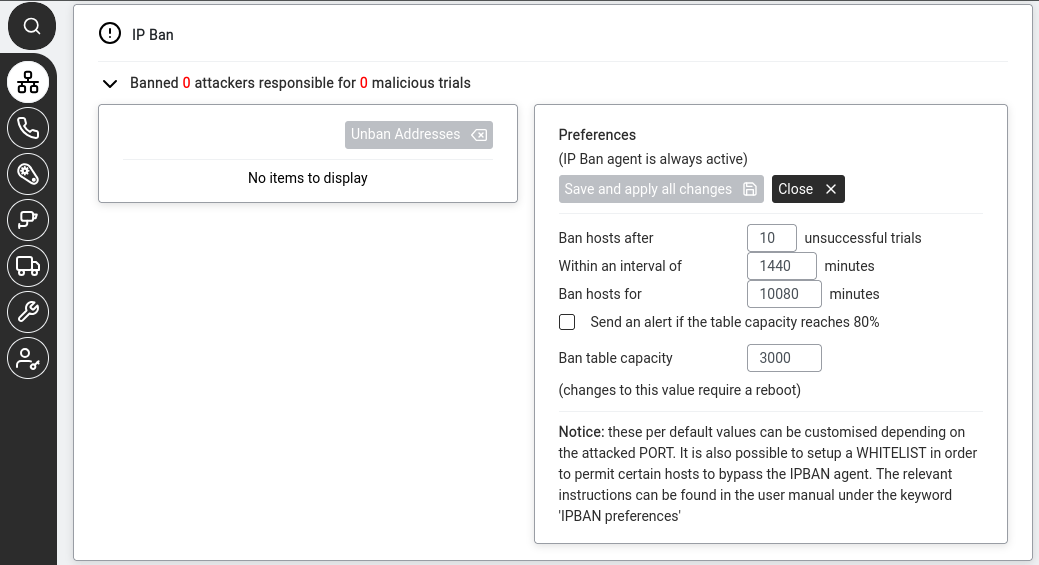
Goal: Automatically blocks IP addresses that repeatedly fail to log in.
The IP Ban agent is always active — you don't enable it, you configure its sensitivity.
IP Ban — repeated failed logins cause the attacker's IP to be blocked automatically.
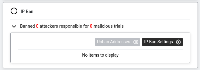
Viewing ban status
Go to Networking > Info, scroll to IP Ban.
IP Ban section in Networking > Info.
The header shows: "Banned X attackers responsible for Y malicious trials".
Expand it to see banned IPs and two buttons:
IP Ban section — Unban Addresses and IP Ban Settings buttons.
Unban Addresses — manually remove a ban (if you locked yourself out).
IP Ban Settings — configure thresholds.
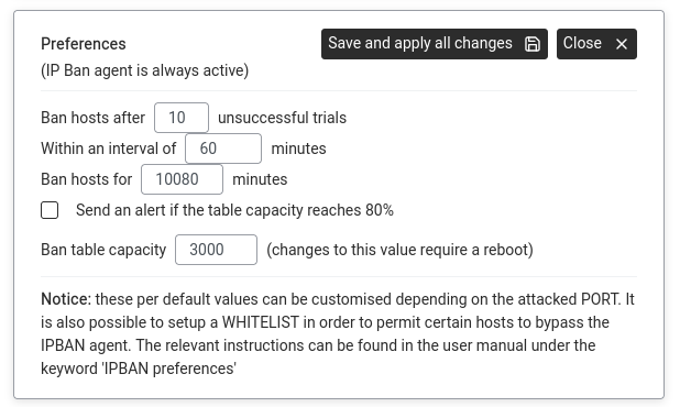
Configuring thresholds
Click IP Ban Settings. The Preferences dialog opens.
IP Ban Preferences — thresholds and ban duration.
Configure:
Ban hosts after10unsuccessful trials
Within an interval of60minutes — 10 failed attempts from the same IP within 1 hour triggers a ban.
Ban hosts for10080minutes (= 7 days)
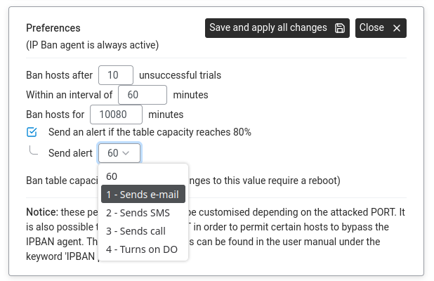
Send an alert if the table capacity reaches 80%Alert channel dropdown — email, SMS, call or digital output. — tick to get warned when the ban list is filling up. Choose alert channel:
1 - Sends e-mail
2 - Sends SMS
3 - Sends call
4 - Turns on DO (digital output)
Ban table capacity:3000 — max simultaneous bans. Changing this requires a reboot.
Click Save and apply all changes.
The notice at the bottom of IP Ban Settings explains that thresholds can be customised
per attacked port, and you can set up a whitelist to exempt certain IPs (e.g. your own office).
Both are CLI-only — see the
v9.0 reference manual
under keyword IPBAN preferences.
Advanced: CLI equivalent
The CLI command sequence for this task is documented in
Chapter 83.33 — How to prevent brute-force attacks of the old Abilis manual.
A rewritten CLI guide is in preparation; this link will be updated when it is ready.
Get notified when a new device appears on your network
Goal: The Abilis continuously scans your LAN for devices using ARP.
You can see every connected device and set up alerts for unknown ones.
ARP alert — the Abilis detects unknown devices appearing on your network.
Viewing connected devices
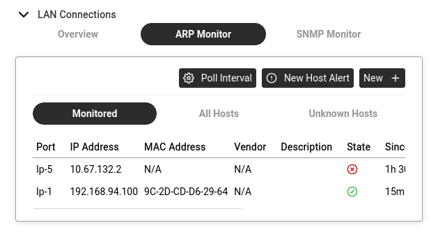
Go to Networking > Info > LAN Connections > ARP Monitor.
Monitored — devices you are watching. Columns: Port, IP Address, MAC Address, Vendor, Description,
State (green tick = up, red cross = down), Since, Max down (sec). Edit/delete buttons on each row.
All Hosts — every device ever seen on the network.
Unknown Hosts — devices not in your monitored list. Each row has + Add To Monitor.
Setting up alerts
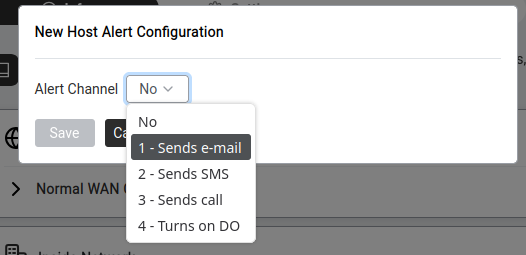
Click New Host Alert (top right).
New Host Alert — choose the notification method.
Choose alert channel: No, 1-Email, 2-SMS, 3-Call, 4-Digital Output.
Click Save.
Adding a device to monitoring
Either click + Add To Monitor on an Unknown Host, or click New + to enter details manually.
Set IP, MAC, description and monitoring parameters.
Click Save.
Practical workflow: check Unknown Hosts regularly. Click Add To Monitor
on devices you recognise. Any device you don't recognise is worth investigating.
Goal: Lets you watch specific services on network devices (switches, printers, servers)
and get alerted when they go down. The Abilis periodically asks "are you alive?" and raises
an alarm if the answer stops coming.
SNMP (Simple Network Management Protocol) — a standard for monitoring network devices.
The Abilis acts as an SNMP manager that polls other devices for status.
Go to Networking > Info > LAN Connections > SNMP Monitor.
Click New +.
Fill in:
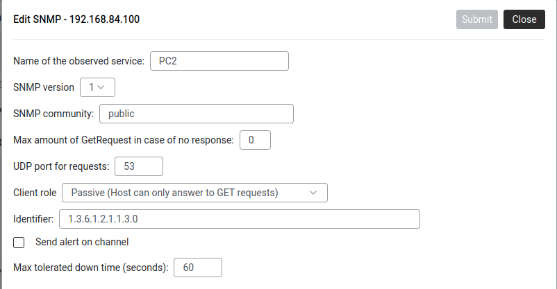
SNMP monitoring setup — service name, community, OID, alert channel.
Name of the observed service: a label (e.g. PC2, PrinterOffice).
SNMP version:1 is simplest. Use 2c or 3 if the device requires it.
SNMP community: the shared passphrase — usually public (read-only). Must match the device.
Max GetRequest retries: how many times to retry if no response (0 = no retries).
Client role:Passive (Host can only answer to GET requests) — the safe default.
Identifier: the SNMPOID to check. 1.3.6.1.2.1.1.3.0 = system uptime — a universal health check.
Send alert on channel: same options (email, SMS, call, digital output).
Max tolerated down time: seconds before alert fires (e.g. 60).
Click Submit.
The SNMP Monitor tab shows each service with State (green tick / red cross).
When a service goes down and stays down past the tolerated time, the alert fires.
Advanced: CLI equivalent
The CLI command sequence for this task is documented in
Chapter 84.27 — How to activate the SNMP agent of the old Abilis manual.
A rewritten CLI guide is in preparation; this link will be updated when it is ready.
Access your own public services from inside the network (NAT loopback)
Goal: Fixes a common problem — you've set up port forwarding so your camera is
accessible at myoffice.ddns.net:8080 from the internet. It works from home. But from inside
the office, the same address doesn't work.
How NAT loopback works. Without the loopback rule the camera would reply directly to the PC and the connection would break silently.The NAT table. Rule 0 is a DNS redirect (destination NAT), rule 1 is the standard source NAT (INSIDE → OUTSIDE) and rule 2 is the loopback source NAT (OUTSIDE → INSIDE) that lets internal devices reach internal services via the public IP.
Why: Your PC sends the request to the Abilis's public IP. The Abilis sees it came
from inside the LAN but is addressed to the outside — it doesn't know to redirect it internally.
When you need it: Only if internal devices need to use the public IP or domain name.
If everyone inside uses the device's internal IP directly (e.g. 192.168.1.50), you don't need this.
NAT loopback requires a Source NAT rule with both zones set to INSIDE.
This rule rewrites the sender's address so that the internal server's reply routes back
through the Abilis (instead of going directly to the client, which would break the connection).
This rule works alongside your existing Destination NAT port forwarding rule.
The port forwarding rule handles the incoming connection; this Source NAT rule ensures
the reply goes back through the Abilis so internal clients can reach the service
using the public address.
Advanced: CLI equivalent
The CLI command sequence for this task is documented in
Chapter 84.16 — How to configure the NAT loopback of the old Abilis manual.
A rewritten CLI guide is in preparation; this link will be updated when it is ready.
Goal: Enables bandwidth monitoring on a network port so you can see
Line Load graphs and Top 5 usage charts for that connection.
TRFA is enabled per port — you choose which connections you want to monitor.
Go to Networking > Settings > Ports.
Click on the port you want to monitor (e.g. your WAN port).
Tick Advanced to see all options.
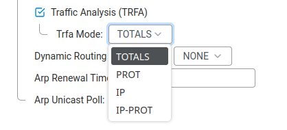
Scroll down to Traffic Analysis (TRFA) and tick the checkbox to enable it.
Set the Trfa Mode to choose the level of detail:
Trfa Mode options — from basic totals to full per-IP protocol breakdown.
Mode
What it records
Best for
TOTALS
Total global traffic on this port.
Simple "how much bandwidth am I using?" overview.
PROT
Traffic broken down by protocol (TCP, UDP, etc.).
Understanding what kind of traffic flows through.
IP
Traffic totals per individual IP address.
Finding which device uses the most bandwidth.
IP-PROT
Traffic per IP address, further split by protocol.
Full detail — which device is doing what. Uses the most disk space.
Click Save.
Repeat for any other ports you want to monitor.
Once TRFA is active on a port, traffic data starts collecting immediately.
You can view the results at Networking > Info — see
View traffic analysis below.
Advanced: CLI equivalent
The CLI command sequence for this task is documented in
Chapter 84.24 — How to activate the IP TRFA resource of the old Abilis manual.
A rewritten CLI guide is in preparation; this link will be updated when it is ready.
View traffic analysis (Line Load and Top 5)
Goal: See how much bandwidth each connection is using right now and which devices on your network are consuming the most traffic.
Go to Networking → Info. Click on any connection (e.g. Lan_locale).
You'll see two tabs at the top: Line Load and Top 5.
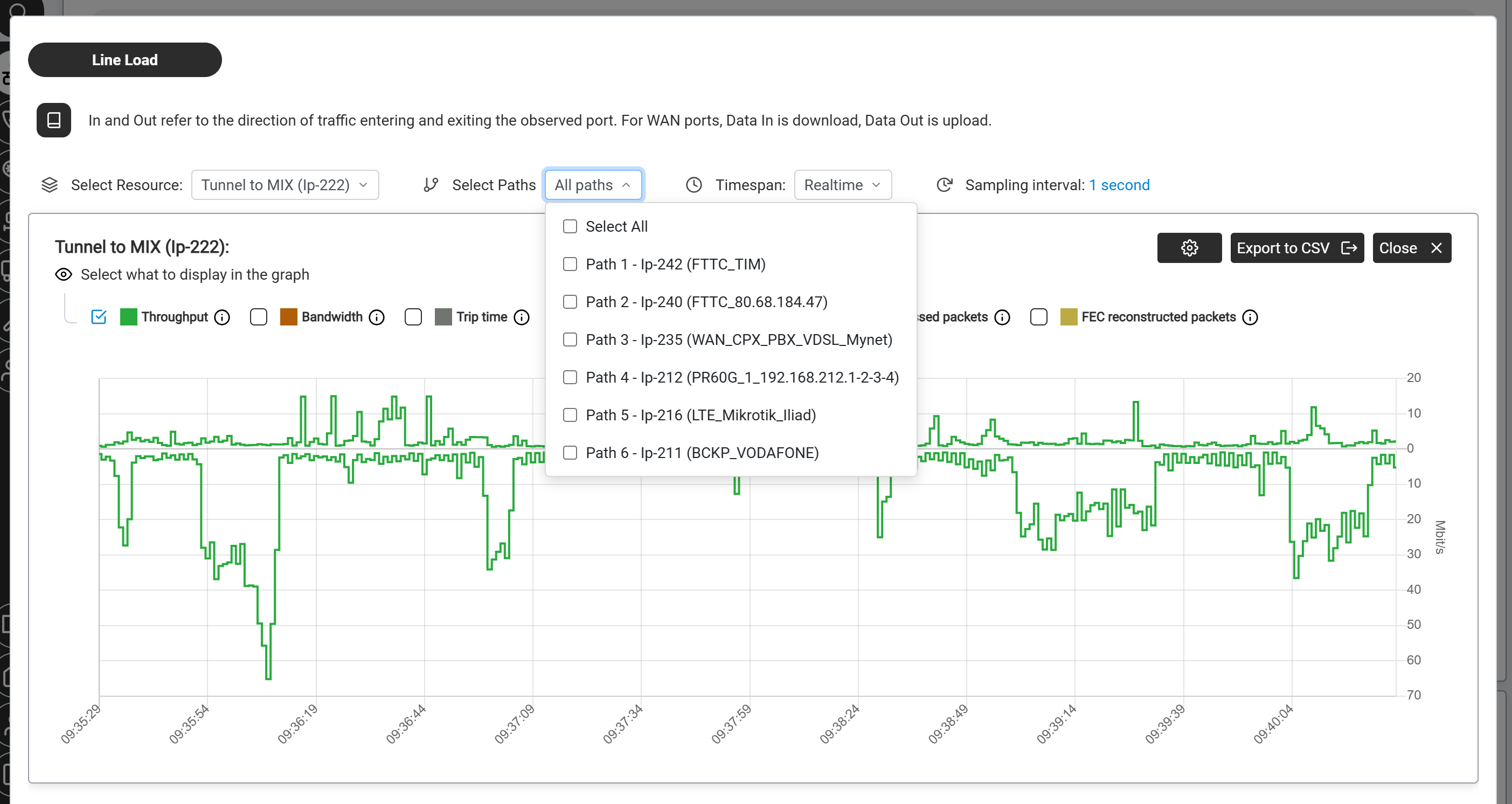
Line Load — a real-time throughput graph showing how much data is flowing through the connection over time. Use the dropdowns at the top to set:
Select Resource — the connection to view (tunnel, WAN bundle or LAN port).
Select Paths — located directly next to Select Resource. On a multi-path resource (an AIPT2 tunnel or WAN bundle carries up to 6 paths), pick one path, several or All paths. Selecting more than one plots them on the same graph so you can compare them side by side — useful for spotting which path is degrading during a fault.
The Select Paths dropdown on a multi-path resource, listing each path of the AIPT2 tunnel (here Tunnel to MIX, Ip-222). Choose one, several or All paths to overlay them on the same graph and compare them.
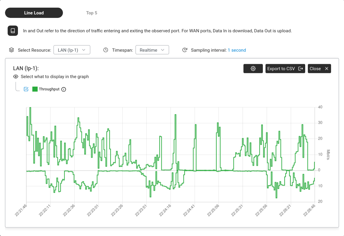
Timespan — Realtime, Day or Week.
The display toggles under the graph (Throughput, Bandwidth, Trip time, sent / received / lost / FEC-reconstructed packets) control which series are drawn.
Line Load — throughput graph for LAN (Ip-1) showing download and upload traffic in real time.
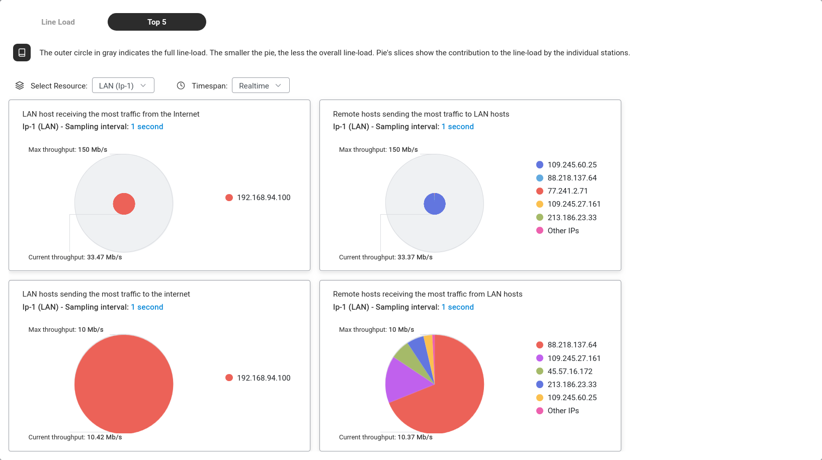
Top 5 — four pie charts showing which devices and remote hosts are using the most bandwidth. The grey outer circle represents the full capacity; coloured slices show each device's share.
Top 5 — the four quadrants show: which LAN device downloads the most, which remote server sends the most, which LAN device uploads the most and which remote server receives the most.
You can Export to CSV from the Line Load view for reporting or analysis in Excel.
Tip: Internet feeling slow? Check Top 5 to see which device is consuming the most bandwidth. If one device is using most of the pie, that's your culprit.
Advanced: CLI equivalent
The CLI command sequence for this task is documented in
Chapter 84.24 — How to activate the IP TRFA resource of the old Abilis manual.
A rewritten CLI guide is in preparation; this link will be updated when it is ready.
Goal: Gives your Abilis a fixed name (like myoffice.ddns.net)
that always points to your current public IP, even when it changes.
DDNS has two parts: the DDNS service (provider credentials) is configured via the
SSH/Telnet CLI as a one-time setup, but the domain name binding is managed through the
web interface.
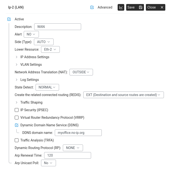
In the DDNS domain name field, enter the hostname you registered with your
DDNS provider (e.g. myoffice.no-ip.org).
Port settings (Advanced) — DDNS enabled with the registered hostname.
Click Save.
The DDNS service itself (provider name, username, password) must be configured once
via the Abilis control program. Once that initial setup is done, the domain name binding
shown above is all you need to manage through the web interface. If you change DDNS providers,
the service credentials will need to be updated via CLI again.
Advanced: CLI equivalent
The CLI command sequence for this task is documented in
Chapter 84.18 — How to setup DDNS service on Abilis of the old Abilis manual.
A rewritten CLI guide is in preparation; this link will be updated when it is ready.
Set up LTE as a backup internet connection (automatic failover)
Goal: If your main connection drops, the Abilis switches to LTE automatically.
Automatic failover — primary line fails, Abilis switches to LTE backup.
How it works: Two default routes with different metrics in the Routings table.
Lower metric = higher priority. The Abilis monitors both and switches automatically.
Go to Networking > Settings > Routings.
You should see your primary default route (destination: any, pointing to your
fibre/DSL port). Note its metric value.
Metric: a value higher than the primary route's, so this route is only used when the primary fails. (Metric is the route's AD; see How the Abilis chooses a route.)
Click Save.
Verify at Networking > Info — you should see both connections,
with the primary showing a green status icon and the backup ready to take over.
To test failover, temporarily disconnect the primary connection. The Abilis should
switch to LTE within seconds. Reconnect the primary and it will switch back automatically.
Goal: A voice tunnel carries phone calls between two Abilis sites.
Extensions at Site A can call Site B as internal calls.
This how-to is for monitoring an existing voice tunnel. To create one,
see Phone How-To → Link two Abilis PBXs
(the configuration lives in the Phone section because it deals with extensions and call routing).
Go to Networking > Info. Click on the voice connection (e.g. "VoIP_smartphones").
Line Load shows a throughput graph. Select the resource (e.g. VoIP_smartphones Ip-4) and timespan.
Green line = bandwidth usage. Flat near zero = no active calls; spikes = call traffic.
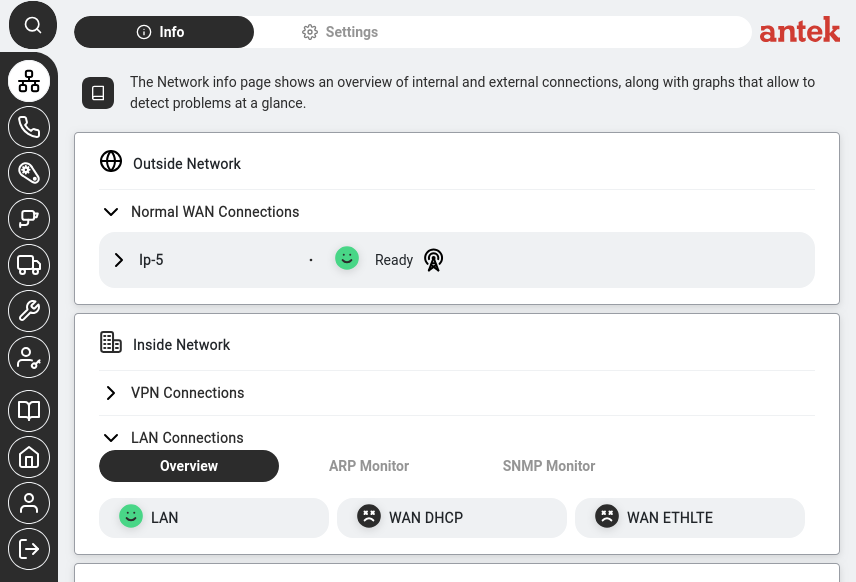
Goal: You want a quick overview of all your network connections — which ones are working,
which ones are down and whether the Abilis is connected to the internet. This is the first
thing to check when something isn't working.
Go to Networking → Info. Click the Networking icon in the sidebar, then the Info tab. The live status dashboard loads automatically.
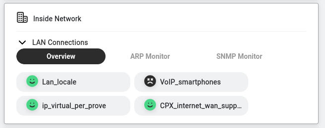
Read the status indicators. Each connection is shown as a pill-shaped button with a coloured icon:
Icon
What it means
Green (happy face)
Connection is up and working normally.
Dark/grey icon
Connection is configured but not currently active — it may be intentionally disabled, standing by as a backup or misconfigured.
Click on any connection to see its detail page, including Line Load graphs (how much bandwidth is being used) and Top 5 traffic sources.
Networking → Info — status indicators show connection health at a glance.
Tip: Bookmark this page or make it your habit to check it first thing in the morning.
If all icons are green, everything is fine. If a connection that should be active shows a dark icon, see
Internet not working — what to check first for next steps.
How QoS works: marking traffic and managing the bottleneck
Goal: Understand the model behind the IPCOS tag and the IP Shaping
panel — why you'd mark a packet HIGH, and what the Abilis is doing when it
throttles a connection.
Why it matters: A link only has so much bandwidth. When it fills up,
something gets delayed — and if that something is a voice call, people hear it.
QoS is how you decide what waits and what doesn't, instead of leaving it to chance.
QoS is three jobs done in order. Think of a busy road: first you sort vehicles into
types (classification), then you put a sticker on each (marking)
so later checkpoints can tell them apart, then at the bottleneck you give some types priority
and hold others back (queuing and shaping).
Classification — deciding which traffic is which (this is voice, that is a
backup job). On the Abilis you classify with a firewall (ACL) rule that matches
the traffic.
Marking — stamping each packet so the decision can be honoured without
re-classifying. The Abilis's mark is IPCOS: HIGH, NORMAL,
LOW or DFT (use the system default class). On other routers the
mark usually travels in the IP header as a DSCP value; the Abilis instead
keeps its own class and copies it into the VLAN (802.1q) priority bits, so
tagged-Ethernet equipment downstream can honour it too. (An ACL rule can
also write the in-header mark directly: its TOS-O field rewrites the
packet's ToS byte — the field that carries DSCP — on the way out.)
Managing the bottleneck — the part people confuse. Two ways to enforce a
limit:
Shapingdelays traffic that exceeds the limit and releases
it a moment later — smooth, nothing lost, a little slower.
Policingdrops the excess immediately — no added delay, but the
dropped packets are gone.
On the Abilis: with classes of service active, packets marked
HIGH are served ahead of NORMAL and LOW when the line is
congested (a balance option keeps the lower classes from being starved entirely).
IP Shaping is the automatic shaper: it watches the heaviest few talkers, and
when one of them is a steady machine-to-machine flow — high volume, low variance: a backup or a
big file transfer, not bursty browsing — it pushes that flow's packets back in the output queue
so interactive traffic goes first. Nothing is dropped, and when the line is otherwise idle the
bulk flow runs at full speed.
Worked example — protect a VoIP call on a saturated WAN:
Classify + mark: add an ACL rule matching the voice traffic and set
IPCOS = HIGH.
When the WAN fills, voice packets jump the queue ahead of default-class traffic —
the call stays clear.
Optionally let IP Shaping hold the bandwidth hog back: a steady upload is delayed (not
dropped) whenever anyone else needs the line.
The rule: classify with an ACL rule, mark what matters
HIGH (IPCOS) and let IP Shaping push steady bulk flows behind interactive
traffic. Shaping delays excess; policing drops it — the Abilis's tools shape.
Goal: Caps the bandwidth on a connection to prevent it from consuming
all available capacity, reserving room for other services (e.g. phone calls, VPN).
Go to Networking > Settings > Ports.
Click on the port you want to limit (e.g. a WAN or tunnel port).
Tick Advanced to see all options.
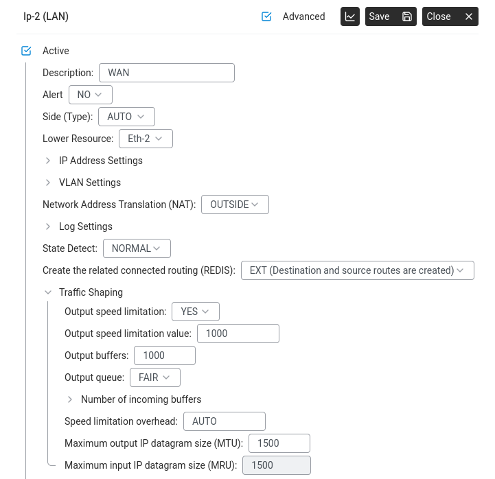
Scroll to Traffic Shaping and expand it.
Set Output speed limitation to YES.
Set the Output speed limitation value in Kbit/s (e.g. 1000 for 1 Mbit/s).
Port settings (Advanced) — Traffic Shaping with output speed limited to 1000 Kbit/s.
Click Save.
This is especially useful on VPN tunnels or WAN connections where you want to
guarantee bandwidth for voice traffic. Limit the data tunnel so it can't starve
the voice tunnel.
Cap bandwidth per IP address or subnet (IP Shaping)
Goal: One device or one department is saturating the internet line
— a backup job, a single heavy downloader, a guest VLAN hogging everything. Rather
than limit the whole WAN port (see traffic shaping for
that), you want to cap specific hosts or networks so everyone else keeps
their share.
Networking > Settings > IP Shaping. Set the upload and download thresholds above which a host is throttled, the variance window and how often the rate is adjusted.
IP Shaping — an Abilis feature that enforces a
maximum bandwidth rate per IP address, per subnet or per matching rule. Different
from the ACL firewall (allow/deny): IP Shaping doesn't block anything, it just
limits speed.
Identify who to limit — the offending IP, a list of IPs or a subnet
(e.g. the guest VLAN192.168.100.0/24).
Go to Networking > Settings > IP Shaping.
Click New + and configure the rule:
Source: the IP, subnet or a list
of addresses to limit.
Destination: usually any (limit them for all
traffic), or a specific destination if you only care about one direction.
Max rate: the cap in Kbit/s (e.g. 2000 for 2 Mbit/s).
Direction: download, upload or both. For a heavy downloader,
capping download is usually enough.
Click Save. The rule takes effect immediately — no restart.
Verify at Networking > Info — the affected IP's Line
Load will flatten at the rate you set.
The most common real use: create one IP Shaping rule pointing at the
guest-VLAN subnet with a reasonable cap (say 30% of total WAN bandwidth). Guests can
still browse and video-call; they can no longer exhaust the line and starve business
traffic.
IP Shaping and ACL work together, not instead of each other. ACL
decides whether a packet is allowed at all; IP Shaping decides how fast
it flows when allowed. You can combine them — e.g. allow a guest subnet but cap it.
Worked example: machine-to-machine bottleneck
A concrete case Lino described, common in small industrial and office installations:
The situation. A 100 Mbit/s internet line serves a small office.
One of the hosts on the LAN is an industrial PC that periodically uploads large
telemetry or backup files to a supplier's server over the internet — unattended,
machine-to-machine, no human noticing. When an upload runs, the line saturates:
the VPN to the other site stutters, video calls freeze, the cameras' remote viewers
lose frames. The upload itself doesn't need to be fast — it runs overnight by design
— but nothing else works while it does.
The fix. Cap only that machine's outbound rate. Everyone else keeps
full access to the line. The upload still completes (just over a longer window); the
other services stay smooth throughout.
Identify the machine by its static IP — for example 192.168.1.50.
If it doesn't have a fixed address yet, reserve one first via
Set up the DHCP server so the shaping rule keeps
targeting the right host.
Decide the cap. For the 100 Mbit/s line in this example, reserving 80 Mbit/s for
everything else leaves 20 Mbit/s for the industrial PC — enough to upload
several gigabytes overnight without noticeable impact on anyone else. Express the
cap in Kbit/s: 20000 for 20 Mbit/s.
Go to Networking > Settings > IP Shaping and click
New +.
Configure the rule:
Source:192.168.1.50 — only this host.
Destination:any.
Direction:upload. The uploads are the
problem; incoming traffic on this host is negligible.
Max rate:20000 Kbit/s.
Description:industrial_PC upload cap.
Click Save.
Verify: when the next upload runs, open
Networking > Info and select the WAN port. The Line
Load graph should show a flat plateau at ~20 Mbit/s rather than the previous
spike to line rate. Meanwhile the VPN tunnel and voice traffic stay smooth —
the other 80 Mbit/s is there for them.
If the cap turns out too tight and uploads start missing their overnight
window, raise it (e.g. from 20000 to 40000 Kbit/s) and re-check. IP Shaping rules take
effect immediately, so tuning is a matter of minutes, not reboots.
The same shape solves other machine-to-machine squeezes: a CCTV
exporter uploading footage to cloud storage, a store's POS system pushing end-of-day
batches, a backup appliance syncing overnight. The pattern is always the same — pin the
heavy sender to a bounded share, give everyone else breathing room.
Goal: One of your network connections is stuck — a WAN line, a VPN tunnel,
or an LTE uplink — but the Abilis itself is still reachable. You want to recycle just that
one resource without rebooting the whole appliance.
How it works: Restart is done by toggling the resource off and on
— deactivate, save, then reactivate. The resource is torn down and rebuilt
cleanly without affecting any other port on the appliance.
Go to Networking > Settings > Ports and open the
resource you want to restart (e.g. Ip-40, Ip-4 VoIP_smartphones,
an LTE port).
At the top of the resource panel, untick Active.
Click Save. The resource goes down — its status icon changes and its
traffic stops.
Wait a few seconds, then tick Active again and click
Save. The resource comes back up and re-establishes its connection.
Check the result on Networking > Info — the status icon
for the resource should return to green within 30–60 seconds for a normal WAN, or up
to a couple of minutes for an LTE modem that has to re-register on the mobile network.
If the connection doesn't come back: the problem is not on the Abilis side —
it is the upstream device, the operator or the physical link. Check any other resource
sharing the same cable or modem, and the LEDs on the external equipment, before calling
Anteklab support.
Internet is not working — what to check first
Goal: A user reports "the internet is down." Before calling support, you can quickly check
a few things from the Abilis web interface to understand what's happening and possibly fix it yourself.
Troubleshooting flow — follow these steps when the internet is not working.Networking > Info — status indicators showing connection health. Green smileys = connection is up. A red smiley means that connection has a problem.
Step 1: Can you reach the Abilis?
Open your browser and go to the Abilis web address (factory default: https://192.168.1.1).
If the Abilis login page appears, the Abilis itself is fine — the problem is between the Abilis and the internet. Continue to Step 2.
If you can't reach the Abilis at all, the problem is on your local network (cable unplugged, WiFi down, wrong IP address on your computer).
Step 2: Check the connection status
Go to Networking → Info. Look at the status icons:
What you see
What it means
What to do
All icons green
All internet connections are working. The problem is elsewhere (a specific website may be down, or DNS is misconfigured).
Try visiting a different website. If that works, the original site is down — not your internet.
One connection dark/inactive, others green
One connection failed, but other connections are still working. Internet should still work, but may be slower.
All internet connections are down. This could be a provider-side outage or a widespread issue.
Wait 5 minutes (provider outages often resolve quickly). If it persists, try restarting each modem. If still down, call your internet provider.
Icons green but slow/no browsing
Connections are up but DNS might be blocked or a firewall rule is interfering.
Check Networking → Settings → DNS to verify DNS servers are configured. Check DNS Filtering in Administration — a new rule may be blocking legitimate sites.
Step 3: Check if it's just one computer
Ask another user on a different computer to try. If only one computer has the problem, the issue is with that specific computer (its network cable, WiFi connection or local settings) — not with the Abilis.
Step 4: If nothing helps
If you've checked all of the above and the problem persists, gather the following information before contacting support:
Information
Where to find it
Which connections are up/down
Networking → Info (note the status icon colours)
When the problem started
Ask the user, or check Networking → Info for connection history
Is it all users or just one?
Ask around the office
Abilis firmware version
Administration → System → General Parameters
Send this information to tem@antek.it or call +39 0376 16262,27. This saves time because the support engineer won't need to ask you for it.
Anteklab Technical Support
Email: tem@antek.it
Tel: +39 0376 16262,27