| 2.12. USB devices | ||
|---|---|---|
 | Chapter 2. Abilis hardware |  |
| 2.12. USB devices | ||
|---|---|---|
| | Chapter 2. Abilis hardware | |
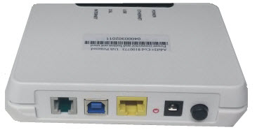
The ADSL USB modem enables one or more ADSL connections (one for each modem) directly on the Abilis without installing any additional router. Up to 8 modems can be installed into the same Abilis.
![[Warning]](../images/warning.png) | Warning |
|---|---|
The number of ADSL StarModem which can be connected to the same USB 1.1 OHCI/UHCI controller is limited. Refer to Section 2.12.1.2, “Isochronous mode” to have more information about isochronous mode. |
![[Note]](../images/note.png) | Note |
|---|---|
The Abilis 5800UB modem is supported starting from Abilis firmware version 7.0. |
![[Tip]](../images/tip.png) | Tip |
|---|---|
Interesting chapters: Section 3.5, “ADSL modem connection”; Section 81.7, “How to configure ADSL connections using USB modems”. . |
| Led | Meaning | State |
|---|---|---|
| Power | Power state. | OFF: USB cable disconnected. ON: USB cable connected. |
| ADSL | ADSL state. | OFF or blinking GREEN: device not able to synchronize. ON: ADSL connection established |
| Data | Data exchange. | Blinking: during data exchange. |
WARNINGS about isochronous mode:
USB 1.1 interfaces are handled with one OHCI/UHCI controller every 2 ports. Usually, the ports that are close each other belongs to the same UHCI/OHCI controller;
USB 2.0 interfaces are handled with one EHCI controller for all the ports. In some rare cases, or when a PCI add on card is used, more EHCI controllers can be present;
Isochronous mode reserves bandwidth on each USB controller. This means that the bandwidth is permanently robbed to other devices connected to the same controller;
The maximal theoretical USB bandwidth on USB 1.1. FULL SPEED is 12 Mbit/sec;
The maximal theoretical USB bandwidth on USB 2.0. HIGH SPEED is 480 Mbit/sec;
Some bandwidth must be left free for the interrupt and bulk transaction;
In Abilis CPX the maximal isochronous bandwidth limit for USB 1.1 is 9.6 Mbit/sec;
In Abilis CPX the maximal isochronous bandwidth limit for USB 2.0 is 384 Mbit/sec;
In Abilis CPX the isochronous bandwidth is dynamically reserved depending on the actual downstream (RX) speed, in 8 discrete steps which are roughly 1,2,3,4,5,6,7,8 Mbit/sec.
As a result, there is a limitation to the number of ADSL StarModem which you can connect to the same USB 1.1 OHCI/UHCI controller, as well as combination of StarModem with UMTS-BOX/BOX2, for example:
One StarModem at maximal speed and one UMTS-BOX/BOX2 are supported within an OHCI/UHCI controller;
Two StarModem connected to 4 Mbit/sec lines and one UMTS-BOX/BOX2 are also supported.
ADSL2+ modem is a USB 2.0 device. Abilis accepts ADSL2+ connection to UHCI/OHCI (USB 1.1) only if there aren't EHCI (USB 2.0) controllers in the system, and in the other case the connection is rejected and device reset is attempted for two consecutive times. This protection has been introduced to impede an undesired and wrong reconnection and tries to recover it. The protection also adds a limitation: it isn't possible to use for ADSL2+ an additional USB 1.1 hub in the presence of EHCI controller.
| Note |
|---|---|
The Abilis ADSL2+ modem is supported starting from Abilis firmware version 7.5. |
| Warning |
|---|---|
Don't connect the Ethernet and power supply ports. The modem is powered from the USB port. |
| Tip |
|---|---|
Interesting chapters: Section 3.5, “ADSL modem connection”; Section 81.7, “How to configure ADSL connections using USB modems”; Section 80.13, “How to replace ADSL modem with ADSL2+ modem”. |
| Led | Meaning | State |
|---|---|---|
| Power | Power state. | OFF: USB cable disconnected. ON: USB cable connected. |
| DSL | ADSL state. | OFF or blinking GREEN: device not able to synchronize.
ON: ADSL connection established. |
| Internet | Data exchange. | Blinking: during data exchange. |
| Note |
|---|---|
The Abilis VDSL2 modem is supported starting from Abilis firmware version 8.4, while for the 7.10 version it is limited only to ADSL mode. |
| Led | Meaning | State |
|---|---|---|
| Power (BLU) | Power state. | OFF: USB cable disconnected. Blinking: during firmware loading. ON: USB cable connected and modem READY. |
| DSL (GREEN) | ADSL state. | OFF or blinking: device not able to synchronize.
ON: DSL connection established. |
| Internet (YELLOW) | Data exchange. | Blinking: during data exchange. |
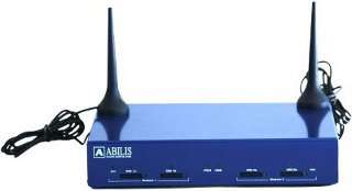
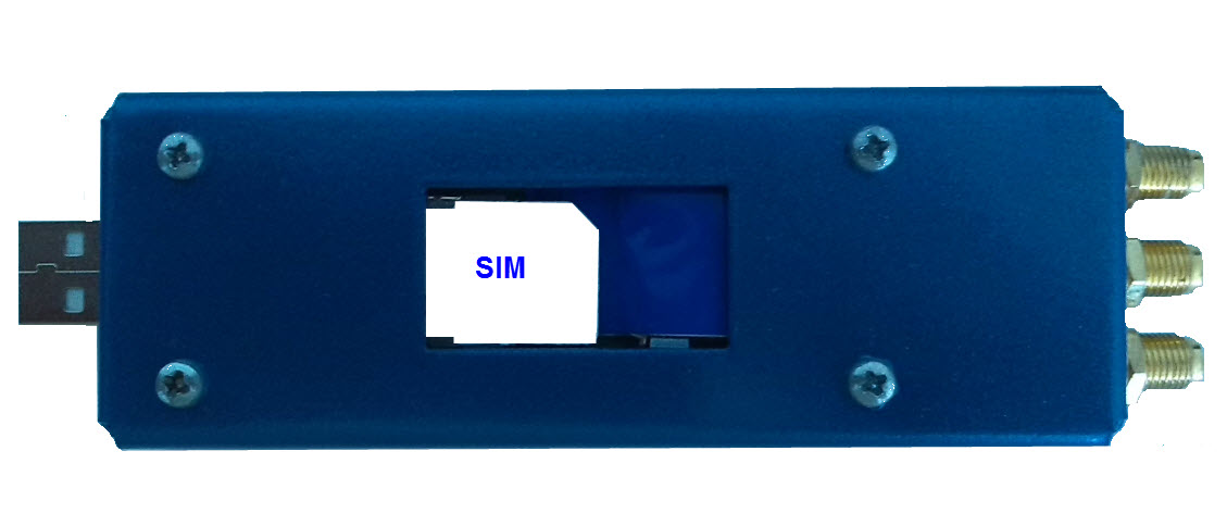
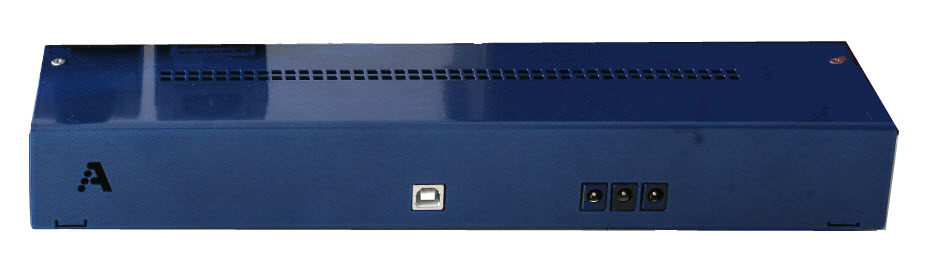
UMTS-BOX2 is a device which provides two independent interfaces to the GSM/UMTS mobile network. It can be connected to ABILIS router through a USB cable and supports full Voice, Data and SMS service.
The most important benefits of SIM remotization are:
Centralization of the SIM when a number of UMTS-BOX2 are dispersed in branch offices;
The management of SIMs is very malleable because the association between SIM and UMTS-BOX2 can be changed using software commands;
The association between SIM and UMTS-BOX2 can be changed by external applications that follow arbitrary customer rules.
The following steps are executed when connecting umtsbox2:
UMTS-BOX2 gets connected to Abilis after 15 seconds when UMTS-BOX2/Abilis boots.
Once UMTS-BOX2 gets connected, the communication with Abilis starts after 5 seconds.
If Abilis doesn't drive UMTS-BOX2, UMTS-BOX2 waits 40 seconds and then resets itself. After the reset, the procedure starts from point #1.
If Abilis drives UMTS-BOX2 and the SIM-container is inside the module and a SIM isn't in the container, the module resets itself.
| Note |
|---|---|
The UMTS-BOX2 is supported starting from Abilis firmware version 6.5. |
| Tip |
|---|---|
Interesting chapters: |
| Led | Meaning | State |
|---|---|---|
| Act(Module1/Module2) | UMTS module activity. | OFF: module off or inactive. ON: module ON, not registered with the network or communicating. ON FLASHING: module ON, registered with the network but inactive |
| SIM 1a/1b/2a/2b | Presence of SIMs inside 1a/1b/2a/2b slots | ON: SIM inserted while UMTS module is reading the SIM. OFF: not inserted SIM or not selected SIM or SIM remotization active. NOTE: The LED is OFF even if the SIM is inserted and the UMTS module isn't reading the SIM. |
PWR USB | Power state USB state | PWR OFF and USB OFF: power cable may be correctly connected but it doesn't matter; USB disconnected. PWR OFF and USB ON: power disconnected or USB not driven by software; USB connected. POWER ON and USB ON: power correctly connected; USB connected and driven by the software. NOTE: If USB cable is disconnected, PWR led is always OFF even if the power cable is correctly connected. |
Dimensions: 234x163x45;
Weight: 1.20Kg.
Power is provided both via USB to HUB, CODEC and PIC and with the additional power cable to SimCom modules. SimCom modules absorb some current from the USB anyway, because of an internal -USB-powered- USB-to-serial converter interface chip.
Table 2.17. Power consumption on the USB
| Device status | Supply voltage (V) | Consumed current (mA) |
|---|---|---|
| USB connected, modules powered down | 5 | 185 |
| USB connected, module1 powered up | 5 | 285 |
| USB connected, module1 and module2 powered up | 5 | 385 |
Table 2.18. Power consumption on the Power supply cable
| Device status | Supply voltage (V) | Consumed current (mA) |
|---|---|---|
| Modules in power down | 5/12 | 100/50 |
| Both modules in standby | 5/12 | 250/100 |
| Both modules during a phone call | 5/12 | 650/300 |
| Both modules during HSDPA download, 23dB power (max power) | 5/12 | 1900/640 |
The LTE-BOX allows to exchange Data, Voice and SMS using a CELLKEY driver. It can be used as backup line when the main one fails or as gateway for the Internet, or as SMS gateway, or GSM/UMTS gateway to make calls to mobile numbers, saving you money.
| Note |
|---|---|
The LTE-BOX is supported starting from Abilis firmware version 8.1. |
The LTE-KEY allows to exchange Data and SMS using a CELLKEY driver. It can be used as backup line when the main one fails or as gateway for the Internet, or as SMS gateway.
![[Important]](../images/important.png) | Important |
|---|---|
This module doesn't support the voice traffic! |
| Important |
|---|---|
The LTE-KEY device requires a separate licence in CPX. |
| Note |
|---|---|
The LTE-BOX is supported starting from Abilis firmware version 8.7. |
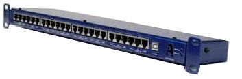
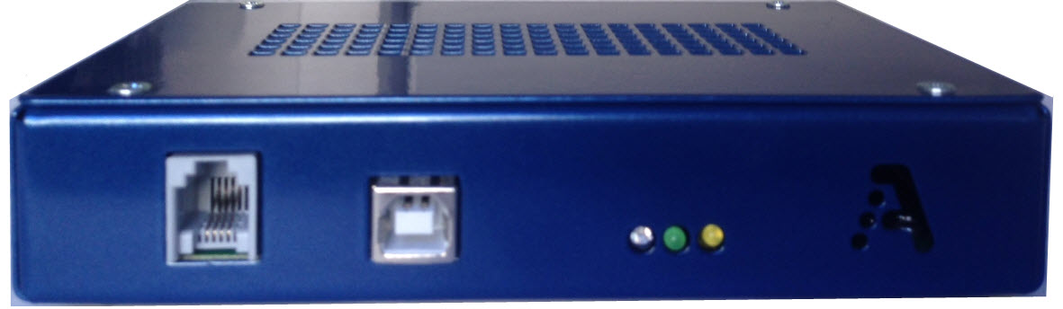
RJS is an ISDN, ADSL or Ethernet switch. It's equipped with:
one USB port;
8 ports (each port includes 3 ISDN/Ethernet ports).
This device checks the keepalive, so if the master (Mx) doesn't reply to the keepalive signal, the link is assumed to be down and the line is switched to the backup device (Bx) until the link is up again.
RJS can handle up to 8 lines.
| Note |
|---|---|
Only the central pins 4,5 and 3,6 are switched! Pins 1,2 and 7,8 aren't connected. Refer to chapter Section 3.10.1, “Connection examples” to have more information about connection. |
There are two versions of RJS:
accepting only 5V power supply;
| Warning |
|---|---|
Connecting a power supply providing more than 5V-DC damages the device! |
accepting 12V power supply.
| Note |
|---|---|
The RJ Switch is supported starting from Abilis firmware version 6.3. |
| Tip |
|---|---|
Interesting chapters: |
| Led | Meaning | State |
|---|---|---|
| Power | Power state. | OFF: external power supply disconnected or faulty. ON: external power supply is connected. |
| Active | Device state. | Blinks fast (0.5 s ON, 0.5 s OFF): Abilis isn't driving the device. Blinks slowly (3 s ON, 3 s OFF): Abilis software is correctly driving the device. |
The RJ Switch is equipped with a PIC microcontroller which controls 8 on-board switches using the control lines. It's installed on the board and it's able to switch each LINE port to the corresponding main port or backup port.
This board contains a watchdog which must be driven by the main Abilis via USB; when the main Abilis stops sending LIVE signals to the board, the PIC understands that the main Abilis is failing and switches the line to the backup Abilis. The board's switch core/watchdog is based on a Microchip PIC18F2450.
| Tip |
|---|---|
Interesting chapters: |
Abilis UPS is available as stand-alone device or embedded in Abilis Base-D model.
When it's embedded it also offers a monitoring interface which is internally connected to a USB port and can be monitored through a specific software resource.
It's also possible to modify some parameters to better satisfy own needs.
The default behaviour is that a periodical sound is emitted during the battery operation and the system is shutdown when the battery level is low. When the main power returns after a battery low shutdown the system will not restart immediately, it will wait until the battery will be sufficiently charged to allow another safe shutdown.
The UPS provides an on/off pushbutton for a complete power on/off of the system, which includes a complete reset of the UPS too. The pushbutton is accessible through a small hole in the cabinet, near the power main connectors.
| Note |
|---|---|
The UPS is supported starting from Abilis firmware version 8.0. |
| Tip |
|---|---|
Interesting chapter: |
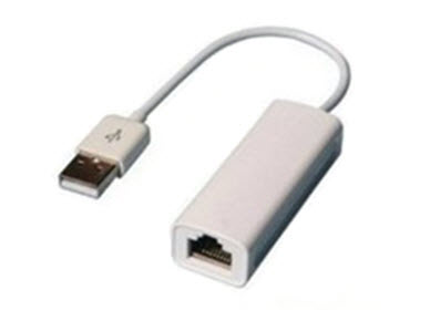
The USB Ethernet is an external adapter that plugs into the USB port of Abilis, to provide an Ethernet port.
| Note |
|---|---|
The Ethernet cable should not exceed maximum length 35m. |
| Note |
|---|---|
The USB Ethernet is supported starting from Abilis firmware version 7.7. |
| Note |
|---|---|
The USB Ethernet supports VLANs starting from Abilis firmware version 8.4.1. |
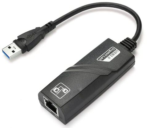
The USB GigaEthernet is an external adapter that plugs into the USB 3.0 port of Abilis, to provide an 10/100/1000Mbps GigaEthernet port.
| Important |
|---|---|
If the USB Giga Ethernet adapter is plugged into the USB 2.0 port it provides 10/100Mbps FastEthernet port. |
| Note |
|---|---|
The Ethernet cable should not exceed maximum length 35m. |
| Note |
|---|---|
The USB GigaEthernet is supported starting from Abilis firmware version 8.5. |
| |  | |
| 2.11. Abilis PCI boards and extension boards |  | 2.13. ELTI devices |