Step-by-step instructions for connecting sensors and relays, building visual control
panels and creating automated rules. The Automation section has four working areas
— Control Panel, Control Loops, Programs,
and Monitoring & Discovery — exposed via six sidebar tabs
(Discovery and Configuration are sub-views of the Monitoring page).
Goal: Connect a WIO (Wireless I/O) module to the Abilis so you can read its sensors (temperature, door contacts, motion) and control its outputs (relays, lights, locks) from the web interface.
WIO (Wireless I/O Module) — a hardware device with digital inputs (DI),
digital outputs (DO), analog inputs (AI) and analog outputs (AO).
DIs read switches/sensors, DOs control relays/lights, AIs read temperature/humidity,
AOs set voltage levels.
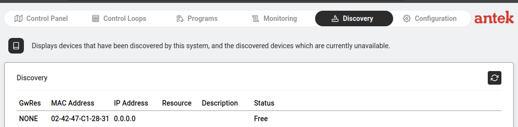
Discovery — a WIO module found on the network. Status: Free (not yet bound).
Go to Automation > Discovery.
The table shows all devices detected on the network: GwRes (gateway resource),
MAC Address, IP Address, Resource, Description,
and Status (Free = available, Bound = already connected).
Click on a Free device to open its settings.
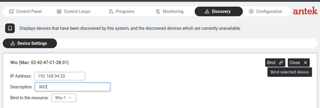
Device Settings — assign an IP, description and bind to a resource (Wio-1).
In the Device Settings panel:
IP Address: assign a fixed IP to the WIO module (e.g. 192.168.94.20).
Bind to the resource: select Wio-1 (or the next available Wio resource).
Click Bind to connect the module to the Abilis.
The module's status changes to "Bound" and its I/O channels become available
in Control Panels, Control Loops and Monitoring.
Build a control panel with buttons and status indicators
Goal: Build a visual dashboard where you can see sensor readings (temperature, humidity, door status) and click buttons to control outputs (lights, gates, heating) — all from your browser, without writing code.
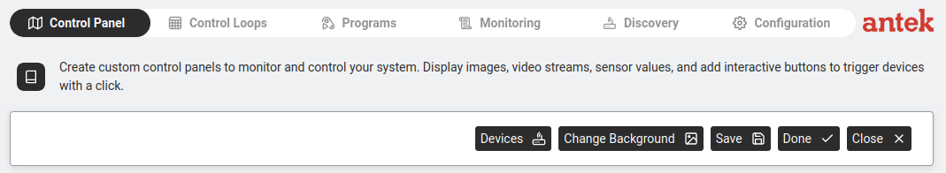
Control Panel in edit mode — Devices, Change Background, Save, Done buttons.
Go to Automation > Control Panel.
Click New to create a new panel (or open an existing one).
You enter edit mode with a toolbar at the top:
Devices — opens the device selector to pick which I/O channels to show on the panel.
Change Background — upload a floor plan image, photo or diagram as the panel background.
Save — saves the current layout.
Done — exits edit mode and shows the live panel.
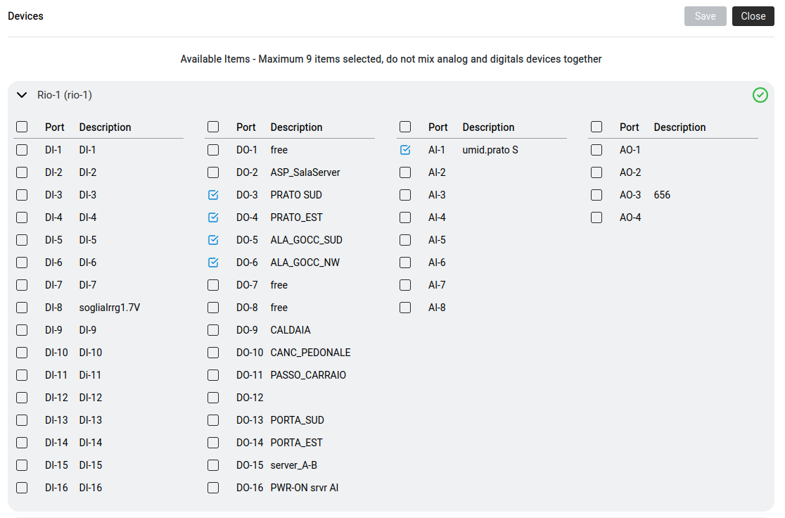
Click Devices to select which inputs and outputs to place on the panel.
The device selector shows all bound modules with their channels in four columns:
Column
Type
What It Does
DI
Digital Input
Reads on/off state (door sensor, button, motion detector)
DO
Digital Output
Controls on/off (relay for gate, light, alarm)
AI
Analog Input
Reads a value (temperature, humidity, voltage)
AO
Analog Output
Sets a value (dimmer level, valve position)
Maximum 9 items selected per panel. Do not mix analog and digital devices in the same panel.
Tick the channels you want, click Save.
Drag the elements on the panel to position them over your background image.
Click Done to view the live panel. DI/AI values update in real time.
Click a DO to toggle it (opens gate, turns on light, etc.).
Create a control loop (if sensor X → then action Y)
Goal: Create an automated rule: when a condition is met (e.g. temperature exceeds 30°C, a door opens after hours, motion is detected), the Abilis automatically performs
an action (turns on a relay, sends an alert). No coding required — the Abilis generates
the LUA script for you.
Control loop — a sensor reading triggers an automatic action when a condition is met.
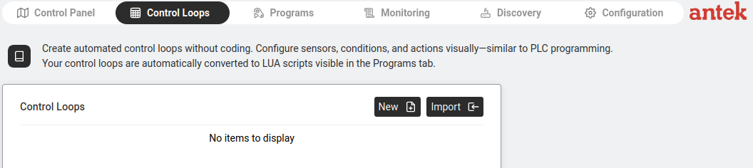
The Abilis describes this as: "Create automated control loops without coding.
Configure sensors, conditions and actions visually — similar to PLC programming.
Your control loops are automatically converted to LUA scripts visible in the Programs tab."
Control Loops — New and Import buttons. Existing loops listed here.
Go to Automation > Control Loops.
Click New.
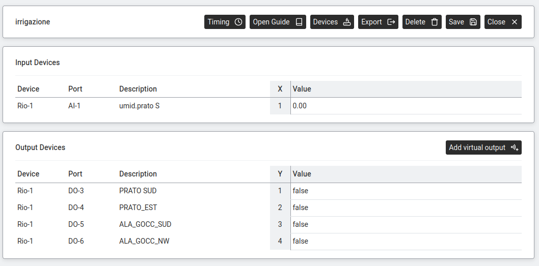
Enter a Name for the loop (e.g. "irrigazione" for an irrigation system). Click Save.
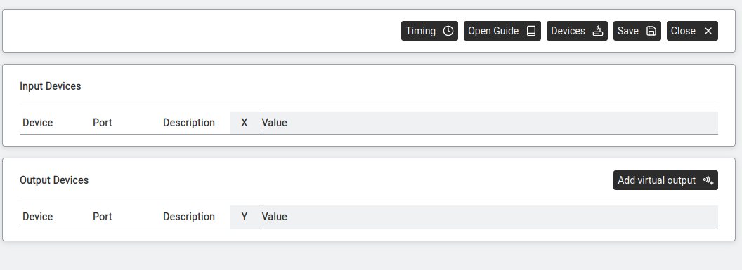
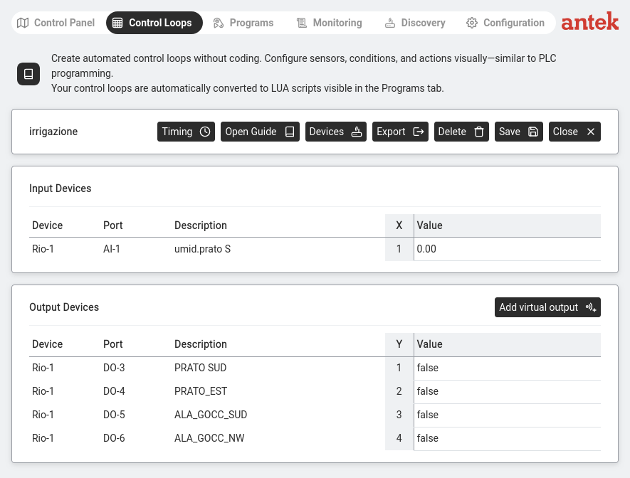
New loop — Input Devices (sensors) and Output Devices (actions) with toolbar buttons.
The loop editor has a toolbar: Timing, Open Guide, Devices,
Export, Delete, Save, Close.
Two sections below:
Input Devices — sensors that the loop reads. Each input gets an X variable number (X1, X2…) and shows its current Value.
Output Devices — actuators that the loop controls. Each output gets a Y variable number (Y1, Y2…) and shows its current Value (true/false for digital, numeric for analog).
Adding devices to the loop
Click Devices. The device selector opens.
Device selector — all channels from all bound modules. Max 9 items, no mixing analog+digital.
Tick the channels you need as inputs and outputs. For example:
Loop with input (AI-1, X=1, value 0.00) and outputs (DO-3 to DO-6, Y=1 to Y=4, all false).
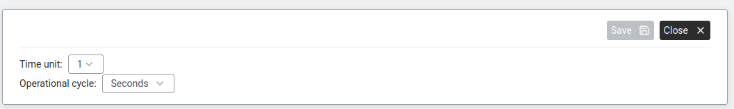
Setting the timing
Click Timing.
Timing — Time unit and Operational cycle (how often the loop runs).
Set the Time unit and Operational cycle (e.g. 1 Second means the loop checks every second).
Click Save.
Writing the formula
Click Open Guide to see the formula editor. The formula uses X and Y variables
you assigned to define the logic. For example:
Y1 = X1 < 30 means "turn on output Y1 (valve) when input X1 (humidity) drops below 30".
Click Save. The loop starts running automatically.
The loop is automatically converted to a LUA script and appears in the Programs tab.
You can edit the LUA directly if you need more complex logic.
Set up Alert Manager channels (email, SMS, call, digital output)
Goal: Before any feature in the Abilis — IP Ban, Control Loops, ARP
Alert, VPN monitor, an alarm — can notify you when something happens, you need
an alert channel configured. A channel is a reusable recipe: "send an email to this
address", "send an SMS to this number", "call this phone and play this message",
"turn on this relay". Once defined, any feature can attach to it.
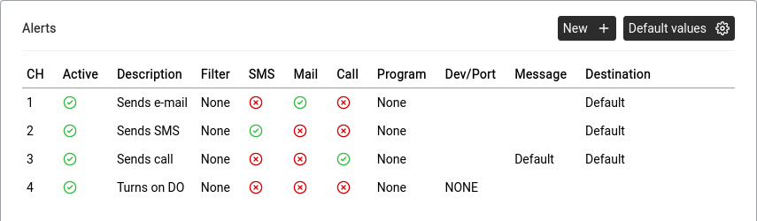
Tools > Alert Manager. Each row is a channel. Green icons show which action types are enabled for that channel (e-mail, SMS, phone call, automation device).
Why channels exist separately: so you configure the recipient details
once and point many features at the same channel. When the manager's mobile
number changes, you edit one channel — not every alarm rule that referenced it.
Go to Tools > Alert Manager.
You see a list of existing channels (CH: 1, CH: 2, …). Click an existing channel
to edit it, or New + to create one.
For the channel, give it a clear Description — e.g. SMS to
manager, Call security, Email IT team. You will see this
name everywhere the channel is referenced.
Tick the output methods this channel should use. You can tick more
than one — a single event can simultaneously email IT and SMS the on-call engineer.
Method
What it does
What to configure
E-mail
Sends an email to a configured address.
Recipient email. SMTP settings must be configured system-wide.
SMS
Sends an SMS through the Abilis SIM modem.
Recipient phone number. The SIM must be installed and registered.
Telephone call
The Abilis calls a number and plays a recorded message.
Phone number, DISA service and the audio message to play.
Automation device
Turns on a physical digital output — a siren, a warning lamp, a bell.
Which DO channel to activate, and for how long.
Click Save.
Attach the channel to an event source. For example, at
IP Ban settings the channel number is chosen from a
dropdown; inside a sensor threshold rule the channel
is referenced under Action. You can point the same channel at as many event
sources as you like.
For email and SMS to actually deliver, the SMTP server (for email) and
the SIM modem (for SMS) must be configured and working. The Alert Manager only decides
when to send; the underlying transport has to be alive. You can test by attaching the
channel to a harmless event and triggering it.
Keep a small set of channels with clear names rather than one big channel
per recipient. A channel like Critical: call all managers (email + SMS + call)
reused across all critical events is easier to manage than dozens of per-event channels.
Act when a sensor crosses a threshold (temperature, humidity, light…)
Goal: A real analog sensor is feeding the Abilis a number — a temperature
probe, a humidity sensor, a soil moisture reading, an ambient light meter. You want
something to happen when the number crosses a value: turn on a cooling fan when the
server-room temperature exceeds 25°C, start irrigation when soil moisture drops below
30%, raise an alert when a freezer climbs above -16°C.
Automation > Control Loops > loop detail. Input Devices lists the sensor (here AI-1, a soil humidity probe). Output Devices lists the relays the loop controls. The condition logic is defined in the syntax editor.
This is exactly what Control Loops are for. This section
walks through the most common pattern — a threshold trigger — with a concrete example.
Scenario: a cold-storage room has an analog temperature probe wired to
a WIO module (channel AI-1). A cooling relay is on channel DO-1.
When the temperature goes above −16°C the cooling must come on and an alert must be
sent; when it drops back below −18°C the cooling switches off.
Confirm the hardware is connected and visible. Go to
Automation > Monitoring and check that the temperature
sensor reports a sensible live value — see
Discover and connect a WIO module if it isn't.
Go to Automation > Control Loops and click
New.
Name the loop (e.g. cold_storage) and click Save.
Click Devices and tick:
AI-1 (the temperature probe) — becomes input X1.
DO-1 (the cooling relay) — becomes output Y1.
Click Save.
Click Timing and set the operational cycle — e.g. 10 Seconds
means the loop re-evaluates every 10 s. Cold storage does not need per-second
evaluation.
Click Open Guide (the formula editor) and write the rule. A simple
on/off threshold is a single line:
Y1 = X1 > -16 — cooling on when temperature above −16°C.
For hysteresis (no rapid on/off flapping around the threshold), keep the previous
output state in a memory variable (M1) and gate the comparison on it
— see the Control Loops formula reference
(memory variables and past-value notation) for the syntax.
Click Save. The loop starts running immediately — the cooling
responds to the live temperature reading.
Attach an alert. Open the same loop, find the Alert channel field
(or create a linked alarm entry), and point it at one of the channels you created
in Set up Alert Manager channels. Now when the loop
triggers, you also get an SMS or email.
The same pattern works for many control-loop applications — just adjust
the sensor, the threshold and the output. Common uses:
Ventilation: a fan relay driven by a temperature, humidity or
CO₂ sensor. Fan on above the setpoint, off below a second setpoint (hysteresis).
Irrigation: a water valve driven by a soil-moisture sensor.
Valve opens when soil is dry, closes when watered.
Lighting: outdoor lights driven by a light-level sensor. On at
dusk, off at dawn.
Pumps: a circulation or sump pump driven by a water-level or
pressure sensor.
Heating: a boiler or heating-valve driven by a temperature
sensor. Same shape as the cooling example above, with the comparison inverted.
Control Loops converts the formula to a LUA script automatically, visible under
Programs if you ever want to extend the logic.
Fire a multi-action alarm from a digital input (panic button, smoke, leak)
Goal: A physical contact closes — a panic button is pressed, a smoke
sensor triggers, a water leak detector activates, a door opens after hours. You want
multiple things to happen at once: all the cameras start recording, a call
goes to security, an SMS goes to the manager, a warning lamp comes on. Not a gradual
reaction like a thermostat — a hard trip.
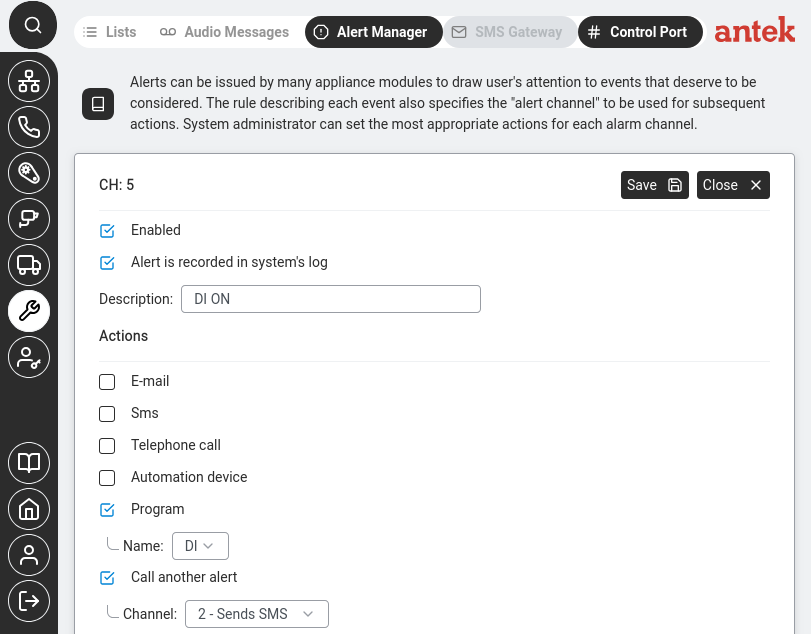
One trigger fans out to every configured action. Each channel (email, SMS, call, relay, program) fires independently.Alert Manager channel detail for a DI alarm. Program is ticked (runs a script named "DI"), and Call another alert chains to channel 2 (Sends SMS) so the admin is also notified by text.
This is different from a sensor threshold rule. Thresholds
run continuously and track a varying analog value. An alarm is a one-shot event:
the input changed, now do these specific actions.
Scenario: a panic button is wired to DI-2 on a RIO module. When
it is pressed, the Abilis must simultaneously (1) call the security company and play a
recorded announcement, (2) SMS the office manager and (3) turn on a red warning lamp
on DO-1.
Create an Alert Manager channel that covers all three reactions at once. Follow
Set up Alert Manager channels and tick
Telephone call, SMS and
Automation device on the same channel. Configure each with its
recipient / output.
Go to Tools > Alert Manager (the Alarm table) and click Add alarm.
Configure the alarm rule:
Trigger source: the device family — RIO,
RVS or WIO (see
Automation Overview for the differences) —
then the channel DI-2.
Condition:on (triggered when the input goes high).
Action: reference the multi-output channel from step 2.
Enabled: yes.
Click Save.
Test — press the button. Within a second or two, the lamp should light, the manager
should receive the SMS and the security company's phone should ring with the
recorded announcement.
The same rule pattern works for the common real-world inputs:
water leak detector on DI, smoke sensor on DI, door contact on DI,
UPS power-fail signal on DI, gate position switch on DI. Swap the source
channel and the action channel — the logic is the same.
To call a list of numbers rather than one (for example, a fire
evacuation announcement to every employee's mobile), see
Make a phone call when a sensor triggers — that
section covers the DISA-callback broadcast pattern, deployed in production to ring 60+
phones simultaneously.
Activate a relay or device from a phone call (gate, bell, door)
Goal: You want a phone call to act as a switch on something physical.
The classic case: a caller dials the Abilis number, the Abilis recognises the caller's
number against an allow-list, activates a relay for a few seconds, and the gate opens
— no apps, no internet, no keyfob, no cloud. Other uses of the same pattern: ring an
external bell when an extension is called, unlock a door by caller-ID, turn on a siren
by dialling a special internal code.
How it works: two Abilis features combine. A CTI routing rule
recognises the incoming call; its output is not another phone but an
automation action — a digital output pulse.
Wire the relay (gate opener, bell, door strike, lamp) to a digital output on a
WIO, RIO or RVS module. Confirm the output works manually from
Automation > Control Panel or Monitoring — you should be
able to toggle it and see the device react.
If you want to restrict who can trigger this — the usual case for a gate — create a
list of allowed caller numbers:
Priority: low enough that it matches before any generic
"route to phones" rule.
Calling number (CGI):list:gate_allowed to require
an authorised number, or * if anyone who knows the number can open it.
Called number (CDI): the Abilis number you want callers to dial.
This can be a dedicated DID, an internal code or any number the SIM/SIP trunk
receives on.
Output (action): select the automation output — your DO channel.
Set the pulse duration (e.g. 3 seconds for a gate strike).
Answer mode: no answer — the call doesn't need to connect for
caller-ID matching. The caller hears a few ring tones and hangs up; the gate
has already opened.
Click Save.
Test — from an allowed phone, call the number. The relay should pulse, the gate (or
bell or door) should respond. Calls from numbers not on the list should be ignored
by this rule and fall through to whatever other routing applies.
Caller-ID is spoofable on some networks. For anything where unauthorised
access has real consequences (front door, safe room, server cage), combine caller-ID
matching with a secondary factor — a short PIN entered after the call connects, a
time-window restriction or a second physical sensor. Do not rely on caller-ID alone as
a security measure.
This pattern is already deployed in production for short-let rentals: the
renter's mobile number is added to the list for the booking window; the gate opens when
they arrive; the number is removed at checkout. No physical key ever changes hands.
Restrict an automation alarm to specific hours or days
Goal: You have an alarm rule that works exactly as intended — a
motion sensor at the perimeter fires an alert and starts cameras recording — but you
only want it active outside business hours. During the day the same motion
is ordinary staff activity and shouldn't trigger anything; at night it matters. One
rule with a time window, not two different alarm systems.
This is the automation-side equivalent of
Night mode for phone calls. Same idea —
a schedule condition on the rule — but applied to alarms from digital inputs and
sensor thresholds rather than CTI routings.
Open the rule in Tools > Alert Manager (the Alarm table).
Find the Schedule or Active hours field on the
rule. Typical options:
Always active (default).
Time window — e.g. MON-SUN,22:00-06:00 for an
overnight curfew, or MON-FRI,18:00-08:00 plus SAT-SUN,00:00-23:59
for business-hours exclusion. Same grammar as
Time/Date Constraints on the CTI Routings page.
Excluded window — the opposite: active except
during the specified times.
Save. The rule now evaluates both the trigger condition and the current
time. Outside the active window the rule is inert — the sensor can fire without
any action happening. Inside the window it behaves normally.
Test at both times. Trigger the source inside the active window and confirm the
alarm fires. Trigger it again outside the window and confirm nothing happens.
For installations with multiple alarm rules that share a schedule —
e.g. a complete "night mode" with six different sensors all active 22:00–06:00 —
configure the schedule once as a named time window in the Abilis's scheduling system,
then reference that window from each rule. Changing the curfew hours later is a
one-place edit.
Schedule conditions apply to the triggering of the rule, not
to already-running reactions. If a rule triggers at 05:59 and starts a camera recording
configured to run for 10 minutes, the recording completes normally even though the
window closes during it. The schedule gates the trigger, not the response.
Upload and manage automation programs (LUA scripts)
Goal: Upload and manage the LUA scripts that power your automation. Control Loops generate these scripts automatically, but you can also write custom scripts for advanced logic.
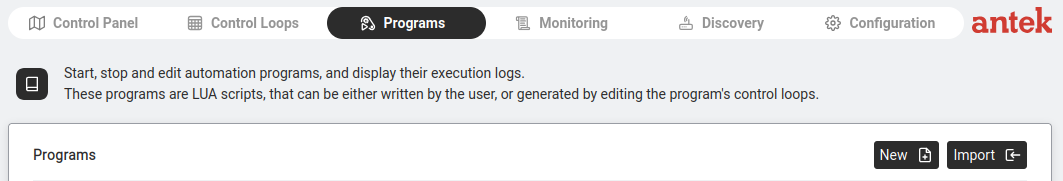
Programs — start, stop, edit LUA scripts and view execution logs. New and Import buttons.
Go to Automation > Programs.
Existing programs are listed with their status (running/stopped).
Click on a program to start/stop it or edit the code. To see what a running program is logging, click the Output button on its row — see the Programs reference page for the full editor walkthrough.
If you used Control Loops, the generated Lua appears here and can be further customised by hand. The Abilis-specific Lua API for talking to automation devices, DISA services and the CLI is documented in the v9.0 reference manual ch58.4 — Lua Abilis extensions.
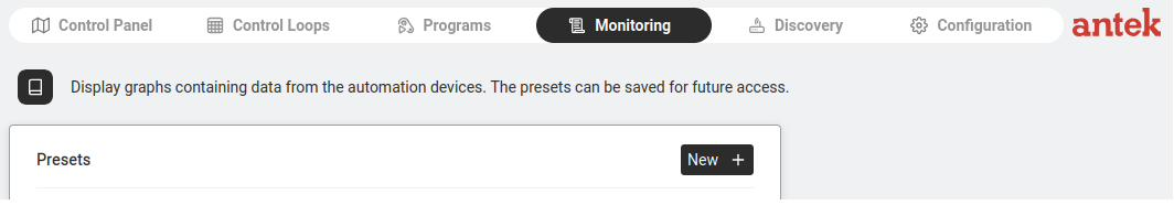
Monitor live sensor values and output states
Goal: Watch live sensor readings in real time — temperature graphs, humidity levels, door open/close events — and set up monitoring presets to quickly check the sensors you care about most.
Monitoring — saved presets appear as named rows (e.g. temper, umid_prato, rvs-1, solar_power). Click a name to open its graph; click New + to create a new one.
Go to Automation > Monitoring.
Click New + to create a new monitoring preset.
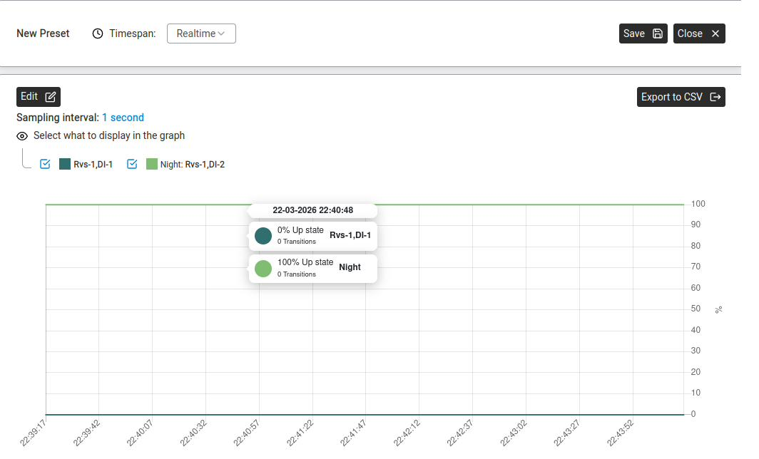
A preset graphing two channels (Rvs-1,DI-1 and Night: Rvs-1,DI-2). The tooltip on hover shows the exact up-state percentage and transition count for each channel at that moment. Edit reopens the device picker; Export to CSV saves the data.
The channel labels are Device,Channel — Rvs-1,DI-1 means digital input 1 on the first RVS module bound to this Abilis. Any free-text prefix you type when creating the preset (here Night:) is just your own label to tell channels apart in the graph legend — it isn't part of the device's address.
The panel shows: "Select a device to start."
Click Edit to choose which devices and channels to graph.
The graph displays live data. Use Export to CSV to download the data for analysis.
Click Save to keep the preset for future access — it appears in the Presets list.
Track equipment run-time for scheduled maintenance
Goal: A piece of equipment — a motor, a compressor, a pump, a
generator, a boiler — needs servicing every N hours of operation, not every N days.
You want the Abilis to track how many hours the machine has actually run
(not just been switched on) and alert maintenance when the interval is approaching,
so nobody forgets and no machine runs past its service window.
Run-time tracking — counting the time a machine is
actively running, by monitoring a digital signal (a relay output from the machine,
or a contact that closes when the motor is on) and accumulating the seconds it has
been active. Different from "power is connected" — many machines idle between
cycles.
Wire the machine's run signal to a digital input on a WIO or RIO module. The
signal source depends on the machine — a motor controller usually has a clean
RUN output relay; an older compressor might need a current-sensing
transformer on the power cable, which produces a contact closure when current is
flowing. Either way, the Abilis sees a simple digital on/off on an input.
Discover the input — see
Discover and connect a WIO module. Note the channel
name (e.g. DI-3) and verify it toggles correctly in
Automation > Monitoring when the machine runs.
Create a control loop for counting. Go to
Automation > Control Loops and click New.
Name it after the machine (e.g. pump_runtime).
Open Devices and add:
The digital input (DI-3) — becomes X1.
An internal accumulator variable (the loop's persistent state) — becomes
M1 (or M2, M3… if you need more
counters), storing total seconds. M values are memory variables that
persist between loop cycles — see
Control Loops → Memory variables (M)
for syntax.
In Timing, set the cycle to 1 Second. Each second the
loop runs, it adds 1 to the accumulator if and only if X1 is active.
In the formula (Open Guide), the logic is:
M1 = M1 + X1 (X1 is 0 or 1; cycle is 1 s; M1 is seconds of
runtime).
Add a threshold condition that triggers an alert when M1 reaches the service
interval in seconds — e.g. 500 hours × 3600 = 1,800,000 seconds for a
500-hour service.
Attach an alert channel — see
Set up Alert Manager channels. The alert fires once
when the threshold is crossed; maintenance gets an email or SMS.
After servicing, reset the accumulator. Open the Control Loop, clear M1 to 0,
save. The counter starts from zero again.
For a fleet of similar machines (e.g. 10 pumps), duplicate the control
loop and change only the input channel and the machine name. All use the same formula;
each tracks its own run-time independently. The maintenance dashboard in
Monitoring can show all counters at once.
Run-time counts continue across Abilis reboots because the
accumulator variable is stored in the unit's persistent configuration. If the Abilis
hardware is replaced, restore from a configuration
backup to preserve the counters — otherwise they reset to zero and the next service
interval drifts.
Anteklab Technical Support
Email: tem@antek.it
Tel: +39 0376 16262,27